I'm having a difficult time getting my newly-built B1 to work. I only connected right in and right out to test. I get power to the board but the only sound I get is buzzing. I've measured all the resistors, the 1M at R200 measures 20k with no power (I don't even have the left input wired). The 10ks at R2 and R3 don't give a steady measurement (the measurements fluctuate without ever landing on one value). I've replaced all three with the same results. Is this normal when they're in-circuit even with no power? My solder connections look okay so I'm at a loss. I've attached pictures of the completed board.
Attachments
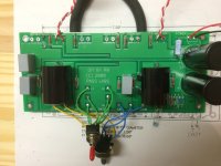
there's an empty hole at the end of the input trace.
Have you wired the vol pot correctly?
The white wire to the RCA is insulated between the red plastic collars.
The input AND the output require a two wire connection.
The white wire is your second wire and MUST be connected to the source equipment output.
The loop area in the RCA connection of red+white is far too big.
The white wire should be right beside the red wire right till it reaches the solder cup and then run alongside the hot pin till it solders to the RCA body right next to the insulator where the hot comes out.
Last edited:
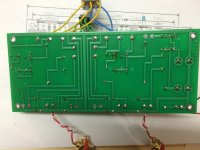
I've just looked at mine and I have the empty holes at the end of the input traces too.
On your photo of the underside of the board, on the side with the blue wires from the pot, follow the straight input trace up from the empty hole to the solder at the other end of the trace. Now go 2 solder joints to the right and zoom in. It doesn't look to be soldered too well to me.
On your photo of the underside of the board, on the side with the blue wires from the pot, follow the straight input trace up from the empty hole to the solder at the other end of the trace. Now go 2 solder joints to the right and zoom in. It doesn't look to be soldered too well to me.
Thanks for the replies...
I've tried to address the issues raised. At least now I can control the volume of the buzz with the pot, but still not getting an input signal. I guess my soldering skills are worse than I thought.
I've tried to address the issues raised. At least now I can control the volume of the buzz with the pot, but still not getting an input signal. I guess my soldering skills are worse than I thought.
I was looking for the DC voltage across the resistor. That way we can know
how much current the circuits are drawing.
😎
how much current the circuits are drawing.
😎
That would be about right, indicating that the Jfets are biased up properly.
Can you measure the DC offset on the Source pins of the JFETs?
(they are the pins that are connected together between the two FETs)
😎
Can you measure the DC offset on the Source pins of the JFETs?
(they are the pins that are connected together between the two FETs)
😎
Is that done by touching the negative lead of the DMM to the gate, and the positive to the source? If so, I get 14.3, 14.1, 14.2 and 14.2 mV.
There are a couple of joints that look a bit ropey.
I would go over them again making sure you get a nice smooth solder joint covering the pad.
I would go over them again making sure you get a nice smooth solder joint covering the pad.
- Status
- Not open for further replies.
- Home
- Amplifiers
- Pass Labs
- B1 Issue