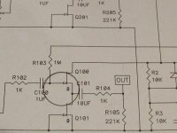
I am making a B1 on perfboard. I have smoked the fets. Can someone confirm the orientation. I have assumed that the schematic shows Drain to R103, Gate to R2 and Source to C101.
An externally hosted image should be here but it was not working when we last tested it.

Have you measured the Idss of your jFETs? A successful Idss measurement shows that you know which legs/pins are Drains.
Since most jFETs are electrically symmetrical, you can swap drain and source and repeat the Idss measurement. This will confirm the gate pin. Now compare what you have determined with the actual manufacturer's datasheet. You should see agreement on pins locations.
I failed to follow this through when I first started with jFETs. I didn't blow any, but I got very confused by manufacturers adopting different pin outs.
To92 jFETs seem to come in every variety of pin out available.
BTW,
a 9V pp3/9 battery, a 1k0 resistor and a voltmeter virtually result in a guarantee to never damage your jFETs.
Last edited:
Hi Andrew. Thanks for your reply.
I have seen the datasheet for the pin outs and have assumed that it corresponds with my fets.
What the schematic doesn't show is GDS (like a PCB mask might - but the clone boards don't!)
I will check the idss as you suggest.
Regards.
I have seen the datasheet for the pin outs and have assumed that it corresponds with my fets.
What the schematic doesn't show is GDS (like a PCB mask might - but the clone boards don't!)
I will check the idss as you suggest.
Regards.
UPDATE: I now have a working board (after some "re-organization" - cough, cough....of the components) The magic smoke is still tightly enclosed.
I have no sound at the moment (apart for turn-on thump) but I am not using a pot and so need to look at the wiring again.
I have no sound at the moment (apart for turn-on thump) but I am not using a pot and so need to look at the wiring again.
An externally hosted image should be here but it was not working when we last tested it.
- Status
- Not open for further replies.
- Home
- Amplifiers
- Pass Labs
- B1 Help