Re: Slightly OT, but...
You are welcome. Your pot is actually NOS, had the nickname ''Black Beauty'' and it is chunky. I use one in a tube project of mine. Very good with reliability and tone.
coredump said:
... I've tried this with a QC24 today (basically a pot followed by a 6111WA gain stage), and it seems to work in that context, too. The slight midrange dip, that the pot introduced, went, and a touch of harshness with it. I used two 1M Dale CFM55s in parallel for each channel, the pot is a 47K black Alps (allegedly NOS, but I'm not sure about that).
Excellent hint, thanks Salas.
Best,
Oliver
You are welcome. Your pot is actually NOS, had the nickname ''Black Beauty'' and it is chunky. I use one in a tube project of mine. Very good with reliability and tone.
I'm thinking of making two of these, basically, and using them as a balanced buffer. I could really use such a thing.
Any particular thoughts on this idea? Are there particular sorts of matching about which I should be careful?
Any particular thoughts on this idea? Are there particular sorts of matching about which I should be careful?
You need to match Q100 and Q101 and then Q200 and Q201. But thats it. The big caps can be between 1000uf and 15,000uf or maybe more. Nelson likes to use the Dale RN55 resistors and all resistors are 1/4 watt except R1 which is 3W.
http://search.digikey.com/scripts/DkSearch/dksus.dll?Cat=65538;keywords=rn55
Thats for the Dale resistors
http://www.tech-diy.com/Store/SmallSignal.htm
Thats for the matched 2SK170. Remember you dont need the matched quads just 2 matched pairs.
Uriah
http://search.digikey.com/scripts/DkSearch/dksus.dll?Cat=65538;keywords=rn55
Thats for the Dale resistors
http://www.tech-diy.com/Store/SmallSignal.htm
Thats for the matched 2SK170. Remember you dont need the matched quads just 2 matched pairs.
Uriah
Salas,
Thanks for posting your schematics. I'm going to build this unit as soon as I get my JFET's from Luvdunhill's group buy.
Question for those who like an external psu arrangement.
I know I can either place it in the box or locate it externally. I'm leaning towards putting the psu in a separate box. If I do so, will I need to place some decoupling caps on the rails of the B1 circuitry to keep everything nice and clean sounding?
You are welcome. No big deal really... Did it to share some impressions and to check if an even cheaper, straighter approach could be an option for all. Its a hobby to me, hobby is supposed to be fun. Good luck with your build. Its a very rewarding top value project and it will serve you well. We all must thank Nelson Pass for bringing forward such great and easy stuff to the DIYers. A real gentleman and a guru. Remember that him and John Curl actually invented top audio solid state engineering in the 70s.
If you put the transformer, bridge, and main filter capacitors in a separate box, keep the regs next to the main circuit,and just use 100nF poly caps across LM317 & 337 inputs to ground.
If you put the transformer, bridge, and main filter capacitors in a separate box, keep the regs next to the main circuit,and just use 100nF poly caps across LM317 & 337 inputs to ground.
Salas,
I know this project will bring me much enjoyment. I built a BUF03 preamp in the early 90s and I think it's time for an update.
I've been reading but not posting much until now and I appreciate the sharing of knowledge from Nelson Pass and John Curl. I feel like I've hit the mother lode.
I'll follow up with my impressions of the B1 once I'm done. I just have to wait for those JFETs to arrive...probably October...sigh
Maybe you can make it with 2N5459 until the 2SKs arrive? It will work. And would be interesting for sonic differences report.
Salas,
I will certainly give it a try with the 2N5459. Thanks.
I've got a few parts to buy, but it shouldn't take me long to do a p2p version. Fortuntately, I have a spare xformer and populated psu board handy.
I will certainly give it a try with the 2N5459. Thanks.
I've got a few parts to buy, but it shouldn't take me long to do a p2p version. Fortuntately, I have a spare xformer and populated psu board handy.
Cheap & Cute
Here it is fully boxed. Ready to interface reliably and neutrally whatever source.

Here it is fully boxed. Ready to interface reliably and neutrally whatever source.
salas, nice looking! It fits the supposed "house-doctor" mode in it´s tecno/medical style. Just to bring it with you to different healthy power amps for testing😀
A Buffer question from a total nonelectric: Those 1M Resistors in the Input 100;101, 200; 201 (exactly after every single input) can´t I put just one in front of the Pot?
greets
stefan
A Buffer question from a total nonelectric: Those 1M Resistors in the Input 100;101, 200; 201 (exactly after every single input) can´t I put just one in front of the Pot?
greets
stefan
WRT 1M resistor.. Looks like that would work 🙂
Uriah
edit: Hmm. Looking again and not sure. Would that leave each input that was not "ON" at the time without a 1M? I think so, so maybe you actually do need one for each signal.
Looking more... I am pretty sure you need one from each input. Lets say you had the TV turned on and the Pre set to "CD". What would stop input from the TV making its way to the pot if you didnt have the 1M resistor.
I am so new at this as to have no right posting an opinion, but I am trying to learn and thats the logic looking at the circuit that I see.
Correct, as for the one per input part. Here is where Choky's signature applies ''You edited your question to spoil my answer''.😀
noelectrix said:salas, nice looking! It fits the supposed "house-doctor" mode in it´s tecno/medical style. Just to bring it with you to different healthy power amps for testing😀
Plus non ferromagnetic.
But when it´s not ON, then R is infinite for the source (that is not ON)
stefan
edit🙁two answers meanwhile, you´re very fast )
Thanx
stefan
edit🙁two answers meanwhile, you´re very fast )
Thanx
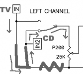
These are just terminal resistors so to avoid thumps when switching inputs due to the fact that the original single rail B1 has an input capacitor. And you need one for each input. At least I guess so.
Nelson can explain what he got with and without them, I never made the single rail B1.
Nelson can explain what he got with and without them, I never made the single rail B1.
I think I have some DC buzz coming through. I was thinking of using a blocking cap but I dont know how to decide which cap to use. Can you guys help me with this?
Uriah
Uriah
Well something does. I have a wallwart as a supply and would rather filter the buzz that I think is the fault of the wallwart than build a new supply that may buzz as well. Also, when I turn the pots ALL the way down, on that last click, they squelch. What I have been told is that this is the fault of DC that wasnt supposed to be there. So, if anyone has a suggestion I would appreciate it.
Thanks
Uriah
I thought that if I had some DC on my house line from a goofy power supply elsewhere in the house that it might make other transformers humm and that would cause the buzzing. That IS right isnt it?
Thanks
Uriah
I thought that if I had some DC on my house line from a goofy power supply elsewhere in the house that it might make other transformers humm and that would cause the buzzing. That IS right isnt it?
- Home
- Amplifiers
- Pass Labs
- B1 Buffer Preamp