Vgs of both jFETs is exactly zero volts. That's the purpose of selecting the jFETs to have the same Idss. Run a jFET at exactly 100% of Idss and the Vgs must be zero volts.
Put that in and you'll see that the source of the upper jFET and the Drain of the lower jFET are at exactly 10k/(10k+10k) * +18Vdc, i.e. 9V
I didn't know that builders were supposed to select Q100/Q101 and Q200/Q201 to have the same Idss. So the gates of Q100 and Q200 are driven positive by the signal?
ok, it pays to read the manual. Mr. Pass says it's best to select them to match...
Last edited:
If you think you haev a superior PSU setup, I encourage you to try it. I believe one that is properly implemented can make a drastic effect. Thhe "Blowtorch" thread reveals thta a great deal of his work on that project concentrated on creating an ideal PSU.
If you think you haev a superior PSU setup, I encourage you to try it. I believe one that is properly implemented can make a drastic effect. Thhe "Blowtorch" thread reveals thta a great deal of his work on that project concentrated on creating an ideal PSU.
I need to figure out how this circuit works in the first place. I can see that by providing a fixed positive bias the need for a negative power supply is not needed in order to allow equal positive and negative voltage swings on the input gate. Coming from the tube world I'm confused by these solid state devices.
It looks like this B1 buffer is most like the circuit (d) with Rs set to zero on both transistors.
Attachments
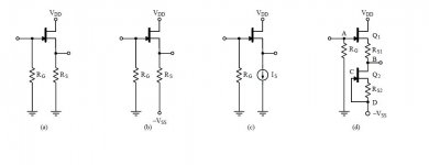
It is (d) without the source resistors and no negative rail. That is why you need matched Jfets. Pretend they were two resistors of the same value. You would have an equal Vdrop across each one as Andrew stated. This is also why, if using a symmetrical supply like the DCB1, you can get away with no output cap. If well matched, the offset should be zero because each fet will be dropping an equal amount of voltage. If it were me and i was interested in the B1, I would try the DCb1.
Last edited:
It looks like this B1 buffer is most like the circuit (d) with Rs set to zero on both transistors.
hmm, maybe more like the variations that followed the B1
I believe they were an attempt to use symmetric +/- supply
B1 have +/0 (ground)
It is (d) without the source resistors and no negative rail. That is why you need matched Jfets. Pretend they were two resistors of the same value. You would have an equal Vdrop across each one as Andrew stated. This is also why, if using a symmetrical supply like the DCB1, you can get away with no output cap. If well matched, the offset should be zero because each fet will be dropping an equal amount of voltage. If it were me and i was interested in the B1, I would try the DCb1.
Well, the gate resistor is tied to +9V in the B1, which is like having a -9V supply and the gate resistor tied to ground as in (d). I'm still surprised that jfets are ok being driven both positive and negative relative to the Vgs bias point. I'm not as adept at solid state circuits... in the tube world bad things happen when the grid is driven positive, so it's a habit of thinking on my part, sorry.
Well, the gate resistor is tied to +9V in the B1, which is like having a -9V supply and the gate resistor tied to ground as in (d). I'm still surprised that jfets are ok being driven both positive and negative relative to the Vgs bias point. I'm not as adept at solid state circuits... in the tube world bad things happen when the grid is driven positive, so it's a habit of thinking on my part, sorry.
Very good point. This is something i learned recently as well. Here is the thread discussing it.
http://www.diyaudio.com/forums/parts/204062-jfet-basics.html
Very good point. This is something i learned recently as well. Here is the thread discussing it.
http://www.diyaudio.com/forums/parts/204062-jfet-basics.html
Thanks. Interesting thread. It's still not clear to me if distortion and noise would be reduced even further if the bias was lowered in the B1. R3 could be made adjustable to set the bias anywhere that I wanted it.
Read Dennis Feucht.
He describes how to set this lower Id version for low distortion and low output offset.
He describes how to set this lower Id version for low distortion and low output offset.
Yes, I read that, thank you. It's different than the B1.
Not really.
Well, besides the fact that the source resistors are zero and the device is operated at Idss, I guess not. One of the references I read says what I thought about operating these things like tubes: always use negative bias otherwise the curves and equations don't apply. But this particular jfet seems to be ok with a few hundred mV of positive Vgs.
Last edited:
True, it does not need a Rolls Royce PSU, but you should hear one(DCB1) first before speaking of quality of sound or lack there of. Too many presumptions!
No-one is going to doubt that either choosing capacitors or eliminating them altogether will affect the sound of the B1 / DCB1.
My comment was regarding PSU noise.
The B1 behaves beautifully with just a reasonable CRC supply.
There is no audible background noise - from my set-up.
Arcam CD36 / B1 / Aleph 4 / B&W 683s
I tried different ps with the B1 (CRC, regulated, shunted), and I found several notorious differences in sound between them, especially at low frequencies, but not in the noise department.
The best sound I got from a ps with the regular B1 is the Sigma11 (Yes, it's a tank and overdesigned for this preamp, but...) The σ11 Regulated Power Supply
I might give it a go.
The current DIY task is to try the SALAS DCB1 shunt regulator with the B1.
Am I correct that the DCB1 runs at 10V ?
The recommended Vcc for the B1 is 18V according to Nelson or 22V if you read these pages.
The current DIY task is to try the SALAS DCB1 shunt regulator with the B1.
Am I correct that the DCB1 runs at 10V ?
The recommended Vcc for the B1 is 18V according to Nelson or 22V if you read these pages.
Last edited:
I certainly heard quite a marked improvement with my CRC supply against the Capacitive Multiplier.
I'm still using CRC with LM317 at the moment but hopefully tomorrow I might get around to building a Shunt Reg.
I'm still using CRC with LM317 at the moment but hopefully tomorrow I might get around to building a Shunt Reg.
Try the Salas BIB regulator it can be set for a wide variety of output voltages.
This Salas reg also works well.
http://www.diyaudio.com/forums/grou...41a-dac-i2s-bus-architecture.html#post2197260
This Salas reg also works well.
http://www.diyaudio.com/forums/grou...41a-dac-i2s-bus-architecture.html#post2197260
Last edited:
- Home
- Amplifiers
- Pass Labs
- B1 Buffer Preamp