I decided to recap my B&W DM6's and have all the new caps installed- but Houston; there is a problem.
There was a contour control & the speakers were fused, I bypassed those & only got sound from the tweeter. I thought if I completed the circuit by soldering a wire from the posts that went to the contour to the pos for the corresponding speaker that I would get sound- no luck!!!
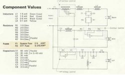
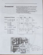
I have attached a diagram of the crossover to see if anyone can help?
There are several post on the web about recapping these speakers, but I could not find one that addressed the problem I am having.
My drivers are all in good working order, the boxes are in great shape and these classic "pregnant penguins" deserve a face lift!!!
I have photos of the work I did if that will help at all- let me know and I will post them.
Thanks, Nut
There was a contour control & the speakers were fused, I bypassed those & only got sound from the tweeter. I thought if I completed the circuit by soldering a wire from the posts that went to the contour to the pos for the corresponding speaker that I would get sound- no luck!!!
I have attached a diagram of the crossover to see if anyone can help?
There are several post on the web about recapping these speakers, but I could not find one that addressed the problem I am having.
My drivers are all in good working order, the boxes are in great shape and these classic "pregnant penguins" deserve a face lift!!!
I have photos of the work I did if that will help at all- let me know and I will post them.
Thanks, Nut
Attachments
Last edited:
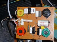
Just to be sure, here are the photos of what I have done thus far.
this is the top view that shows most caps were replaced with Mundorf and all of the caps were bypassed. The second photo shows the posts that go to the speaker terminals and how I ran wire from the posts that went to the tone control/fuses to the pos on the speakers.
this is the top view that shows most caps were replaced with Mundorf and all of the caps were bypassed. The second photo shows the posts that go to the speaker terminals and how I ran wire from the posts that went to the tone control/fuses to the pos on the speakers.
Attachments
Yes, they all worked as did the entire set of speakers; meaning that they produced balanced sound and the fuses and contour worked.
Check with multimeter for continuity of the woofer circuit at the input terminal and read the dcr. Do the same for the midrange at node C3-L3.
Did you cut the transformer wire that goes in parallel with input?
Did you cut the transformer wire that goes in parallel with input?
'soldering a wire from the posts that went to the contour to the pos for the corresponding speaker' - this effectively shorts out the drivers, hope your amp is ok...
It should be the same as completing a circuit, the pos goes to the fuse and has to return to make a connection- is that the way you see it or is there something else?
First it was hooked up without the posts being in the loop, no mid or bass... then with and no mid or bass.
Amp is OK, drivers are OK
First it was hooked up without the posts being in the loop, no mid or bass... then with and no mid or bass.
Amp is OK, drivers are OK
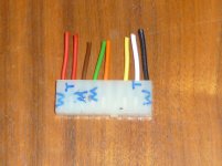
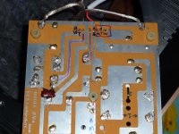
Here is the bottom of the board- it looks like the wires from the contour supply power to the mid and low drivers. The path of the two wires that came from them are highlighted in pink. The Hot posts have a red square around them- see that only the tweeter is directly connected to the Pos (+) coming in. All of the negatives have their own posts.
I would think that if I connected the posts that were for the contour that it should work?
I would think that if I connected the posts that were for the contour that it should work?
Attachments
Can some one please explain the bass section of the contour control? As I read the schematic, there is an auto-former with multiple taps. One of those three taps will be shorted to ground?? I'm clearly missing something about it. 🙂
Thanks,
Erik
Thanks,
Erik
The contours are a twist switch that each have two resistors in them that change the resistance with the different positions. They are R1-4 on the schematic.
Can some one please explain the bass section of the contour control? As I read the schematic, there is an auto-former with multiple taps. One of those three taps will be shorted to ground?? I'm clearly missing something about it. 🙂
Thanks,
Erik
You're basically shifting the "turns ratio" between input and output of the autoformer, thus shifting the input voltage to the bass network. If you redraw it as a transformer, the switch is in effect moving some of the windings from the primary side to the secondary side and vice versa.
Last edited:
The solder joints look like many of them are cold. Add a little rosin flux (not acid) and reheat them. Also it would appear the woofer contour circuit must be installed.
I never would have figured this out, and some pros had a rough time with it. BTW- between the new caps and the upgraded wire, the speakers sound TERRIFIC!
Here is what was done to compensate for the tone controls/fuses:
Here is what was done to compensate for the tone controls/fuses:
Attachments
Last edited:
Erik,
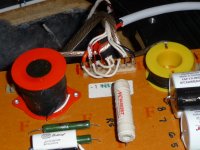
I found out today that it was a transformer that they you saw, it was only on the early speakers as there were two versions.
est, Nut
I found out today that it was a transformer that they you saw, it was only on the early speakers as there were two versions.
est, Nut
- Status
- Not open for further replies.
- Home
- Loudspeakers
- Multi-Way
- B&W DM6 re-capping