What's a reasonable amount of B+ voltage sag for PP AB1?
With a starting (no signal) B+ of 380V, the B+ voltage is sagging to 360V at the onset of clipping using a 1 Khz sine wave. This is a EL34 triode amp with a FWCT SS CLC supply, and a 360V 125ma rated transformer. Bias is 50ma/tube. So, about 20V of B+ sag.
I just tested it with a 350V/175ma rated transformer, and got about 15V of sag between no signal and the onset of clipping.
1.at how many watt's OP is the onset of sag (clipping).
2."have you a schematic".
3.may you could use a V big reservoir cap.
4.have you watered your earthing rod.
2."have you a schematic".
3.may you could use a V big reservoir cap.
4.have you watered your earthing rod.
1.at how many watt's OP is the onset of sag (clipping)?
It's an iteration Poinz' 6GK5/EL34 music machine. Appears to be about 12 watts output based on my beginner calc's. 10 Wrms into 8 ohms=12.5W
2."have you a schematic?".
See posts #6 & #7 here:
http://www.diyaudio.com/forums/tubes-valves/136562-pp-el34-6l6-circuits.html
My PS (for the EL34's) differs from the orig; it is a CLCRC with 2.2 uf, 8H, 220 uf
3.may you could use a V big reservoir cap.
bigger than 220 uf? I'm assuming that my transformer current rating is a little undersized........Is a 1Khz sine wave at the edge of slipping more severe than playing typical music at reasonable levels?
4.have you watered your earthing rod?
That's rather personal, isn't it?😉
with the amount of rain we've just got in So Cal, I'm sure my earthing rod is plenty watered........
Last edited:
I think the power trafo lacks the "stones" needed. Your experiment with bigger "iron" illustrates the situation well.
FWIW, take a look at "El Cheapo". Notice the 100 VA trafo used to provide B+ to 4X "12" W. tubes. That PSU is no small part of the design's success.
FWIW, take a look at "El Cheapo". Notice the 100 VA trafo used to provide B+ to 4X "12" W. tubes. That PSU is no small part of the design's success.
Attachments
Is a 1Khz sine wave at the edge of slipping more severe than playing typical music at reasonable levels?
Yes, but a low-sag supply is worth it. I have switched over to Maida regulators for p-p outputs. My chokes are gone and my capacitors are much smaller. It's more complicated to build but cheaper and better.
Forgot to mention that the 360V/125 ma transformer (and the 350/175 ma transformer) above are powering monoblocks.
Forgot to mention that the 360V/125 ma transformer (and the 350/175 ma transformer) above are powering monoblocks.
The EC supply easily delivers 200 mA. to 4X "12" W. tubes. You have 125 mA. going into 2X "25" W. tubes. Guess where the advantage lies? 😀 Also, EC's supply is quite "stiff", thanks to (sic) 820 μF. caps. in the doubler stack.
if i've got this right......................your load lines are in an area of the graph were the lines merge in to crayon.
so....... have you tried one psu to one mono block and listen to it
{also put a thermometer on the power transfomer}
so....... have you tried one psu to one mono block and listen to it
{also put a thermometer on the power transfomer}
Did you say that you added an extra RC stage for the pentodes? This isn't going to help the output impedance of your power supply, especially if the R is comparable or larger than the DCR of your choke.
That said, a pentode is much more sensitive to changes in the screen voltage than the plate voltage, so if you regulate your screens, you can get away with quite a bit of sag on the plate.
That said, a pentode is much more sensitive to changes in the screen voltage than the plate voltage, so if you regulate your screens, you can get away with quite a bit of sag on the plate.
Yes, but a low-sag supply is worth it. I have switched over to Maida regulators for p-p outputs. My chokes are gone and my capacitors are much smaller. It's more complicated to build but cheaper and better.
Better in what way? Regulators are difficult to get to sound good and Maida don't stand a chance. A shunt reg with a huge sink is a different proposal but it won't be cheap. A reasonable compromise is to feed the input and driver tubes from shunt regs and leave the Maida for the screens.
so....... have you tried one psu to one mono block and listen to it
Yes, I only have one monoblock built, with one 350V/125ma transformer, the second mono block is under construction.
Wavebourn: That's exactly my question.....is 5% reasonable? I suppose it's not too bad...I'm going to check my baby huey today for sag just for fun. Maybe I should have started this thread with "is 5% voltage sag reasonable for hifi?"
Torrence: The outputs are wired as triodes (so no screen supply), and are being fed by a the CLC values above. There is an additional RC stage to drop and smooth the V for the 6GK5's.
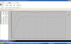
I'd be more interested in knowing what it does at 20 Hz than at 1 kHz. Run it near clipping into a load and monitor the B+ line for signal using a 'scope. That will tell you whether the PS has sufficiently low output Z (current capability) for loud musical passages.
I'd be more interested in knowing what it does at 20 Hz than at 1 kHz. Run it near clipping into a load and monitor the B+ line for signal using a 'scope. That will tell you whether the PS has sufficiently low output Z (current capability) for loud musical passages.
At 20hz sine wave, it's still about 20V of B+ sag at the onset of clipping compared to no signal conditions.
I also did the same test on my baby huey, with much different results...about 2V of sag between no signal and the onset on clipping. So a much stiffer supply..
At 20hz sine wave, it's still about 20V of B+ sag at the onset of clipping compared to no signal conditions.
OK, but if you haven't checked it with a scope, it's not possible to know what's really happening. 20V sag due to transformer resistance, while not ideal, probably won't significantly affect the amplifier's output. However, if it's sagging because the energy "reservoir" is depleting, the voltage reduction may be accompanied by an unacceptable increased in ripple and modulation of the supply by the amplfier. I use a simple voltage divider to inspect B+ supplies with a scope. If you have a schematic of the supply, I'd be glad to Spice it. That's not a substitute for an in-circuit check, but it can help to determine whether the output Z of the supply might be troublesome at lower frequencies.
now I'm really confused.......
I just ran the test again this time using a Triode electronics PA-060 Dynaclone transformer (360V/300ma) and got 15V of sag between no sig and clipping, so I'm beginning to suspect that the transformer is not the issue, since the dynaclone transformer should be much more than needed for a EL34 monoblock.
TriodeKingdom: I do have a scope, and a 600V 10X probe. The ripple V is not getting any larger at clipping than at no sig. If there is other scoping to be done, I'm all ears.
PS PSUDII schematic attached.
Attachments
Hello Boywonder,
In my opinion the sag you are seeing is the amount of sag I would expect to come from the choke when you are fully loaded up at max power and pulling a 100ma of current through the choke. Your results support this as you did see about a 5 volt reduction in drop when running with smallest original power transformer. When you beefed up the transformer the first time you improved from a 20v drop to a 15v drop. Now the principal cause of the drop is the choke and no longer the power transformer. The only way you could reduce the sag further would be to go with a lower choke resistance value. Obviously this sag can be eliminated with a decent series pass regulatore but thats a whole different situation then the one we are discussing.
Mickeystan (aka Doug S.)
The schematic is too low rez to see component values, so I can't Spice it. However, I can tell it's a basic CLC filter. Based on your results with the transformer sub and description of the scope test, I agree with Mickeystan. The sag is very likely to be a combination of the series resistance of the transformer and filter choke. A 15V drop from idle to full load is actually pretty good regulation. I wouldn't worry about unless you have other symptoms.
Power transformers are usually calculated for 10% sag, so 5% sag of an anode supply is quite good. However, I second what was suggested already, about regulated screen grid supply.
Power transformers are usually calculated for 10% sag, so 5% sag of an anode supply is quite good. However, I second what was suggested already, about regulated screen grid supply.
My finals are triode wired............so there is no screen grid supply.
- Status
- Not open for further replies.
- Home
- Amplifiers
- Tubes / Valves
- B+ Voltage sag for AB1 PP