Oops. I meant 10k resistor. Hashimoto does this with their 845 amp as do the Professor series of amps from Japan.
Using high VA transformers, that timer in post #1 wouldn't be any use where I live. The long C time constant in that circuit (C1,2) would keep relay closed some time after mains voltage has dropped. The wobbly plug problem is a nasty test but as it stands would simply blow the primary fuse.
Delayed transformer primary current limiting is the proper approach to avoid repeated fuse blowing on brown-outs and other AC line problems. Post 2ndary regulation can come after. The approach that Morgan Jones gives is one solution, but with considerable complexity.
One is lucky when a street supply is relatively constant; but in the real world this problem is hopelesly ignored.
I will dig out the circuit I regulary use.
richy
Not sure where the warning is here. In the real world, after years of use, a 1.5A fuse has never blown. If I do end up with a wobbly plug (poor design perhaps?) and blow a fuse, this is not a bad thing.
Purpose of the timer is to allow the tubes to heat up before applying B+. Brownouts need not apply, the tubes are already warmed up, and will stay that way for 15 seconds with a complete power outage.
Purpose of the timer is to allow the tubes to heat up before applying B+. Brownouts need not apply, the tubes are already warmed up, and will stay that way for 15 seconds with a complete power outage.
I should have mentioned European line voltages.zigzagflux said:Not sure where the warning is here. In the real world, after years of use, a 1.5A fuse has never blown. If I do end up with a wobbly plug (poor design perhaps?) and blow a fuse, this is not a bad thing.
r:-
In my amp, I use an 8051 to switch a solid state relay on the primary side of power transformers. Very simple electrically, but there is some software to write.
What is the goal in delaying B+? The general thought is that it will avoid cathode stripping, but there are other problems that are created. If you apply power to warm tubes and you have a large time constant in coupling networks, you can couple a nice big current surge of more than a second into the output stage. That can't be good for the power tubes. It is worth considering the possibility that applying B+ to cold power tubes might be easier on them. I don't know. One would have to do an expensive controlled study to know for sure. I'm not willing to fund one.
I opted for total control in my amp. I have it set up with three power transformers; a filament transformer, a high voltage transformer for the voltage amplifiers, and a high voltage transformer for the power stage. I turn on the three in succession. The first transformer to come on is the filament transformer. Then when voltage amplifiers are warm, B+ for them comes on. Bias supply is also on this transformer. After bias and anodes of VAs settle down, I switch on the power tubes. No current surges or cathode stripping(which I am not convinced causes much damage at start-up in these non-transmitting tubes anyway).
rubli said:
Yo man! Have you tested your board with low current pre?
SpreadSpectrum said:What is the goal in delaying B+? The general thought is that it will avoid cathode stripping
I suppose that's a reason for some people. I use it for when I have a quasi-choke input power supply (which is most of the time) coupled with SS rectification (which is some of the time). Without a delay, the B+ would rise to very high values until the power tubes conduct.
Application-specific, but very necessary IMO. Nothing to do with cathode stripping.
Yes, that's a very good reason to delay B+. I just fear that many are running away from the cathode stripping ghost only to meet something worse.
I've been playing with Maida regulators with C-input filters and am very pleased with them. My only complaint is that the damped oscillations from diode reverse recovery make it through to the output. Haven't tried RC snubber yet but I have just completed measuring leakage inductance of the transformers, so that is next. If I can get that out of the output, I will never look back. AB output stages really like the low supply output impedance. I sure don't miss that huge choke.
Nice circuit, by the way.
SpreadSpectrum said:Yes, that's a very good reason to delay B+. I just fear that many are running away from the cathode stripping ghost only to meet something worse.
Un-necessary scare ? My 807 amp uses 450V from 5U4 (practically instant B+) and tubes still have good emission after 50 yrs use with stage vibration. This is no exception.
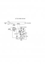
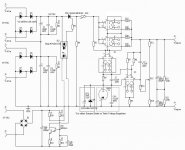
Circuit hints: I use this one for all primary inrush snags from 100-1000VA. It trips out as fast as relay permits i.e small frame relays around 20mS. Thyristor held into conduction by back emf of coil.
richy
Attachments
Un-necessary scare ? My 807 amp uses 450V from 5U4 (practically instant B+) and tubes still have good emission after 50 yrs use with stage vibration. This is no exception.
Circuit hints: I use this one for all primary inrush snags from 100-1000VA. It trips out as fast as relay permits i.e small frame relays around 20mS.
richy
Rich, I like your circuit.
Late question...I have 400Vac approx. B+ 530Vdc for a pair of KT88's. Do I have to consider the choice of relay contacts if ...say I use a 50R/ 50W resistor and want's 10 second delay? What happens upon the relay contact points when the rest of the AC voltage after 10 seconds is connected? Would a 10A/250Vac relay be able to handle the instant draw after the bridge of approx. 200mA? ..and what about the startcurrent?
Could you help me on this one?
Hansen
Depends greatly on the design and transformer. In the case of a ST70, for example, heaters and B+ come from the same transformer. Putting a thermistor in the primary will not only limit the B+, but heater voltage as well. The goal is not to limit heater power during startup, just B+.
What if you put the thermistor on the output side of the transformer?
these come is a wide range of sizes, cold and "hot" resistance and current ratings.
Any ideas on how to size one for proper operation?
What if you put the thermistor on the output side of the transformer?
Depends on your application. If you are talking tube amplifiers, and the 'output side' is the HV secondary winding, then it is unlikely you will get desired performance. Two reasons: for one, most of the available thermistors are rated between 10 and 50 ohms cold. This is not a lot of additional resistance on the secondary circuit, at least not enough to perform effective inrush limiting. Two, the currents required to heat the thermistor and decrease its resistance are normally is the range of an ampere or more. Most secondary windings used in tube circuits do not operate this high, therefore the thermistor effectively is nothing more than a resistor.
They either work best in the low voltage, high current filament windings or with correct sizing can sometimes be applied at the 120V input winding. Based on the ratings, running them between 50% and 75% of rated current is sufficient to limit inrush while getting them hot enough to exhibit the NTC characteristic.
Hello,
I am a fan of soft starts. The lights do not dim when you turn the damn thing on and things warm up in a controlled manner. With the application of an inrush limiter you can select a fuse that will provide meaningful circuit protection even with solid-state diodes.
I am sure that the discussions of cathode stripping and the like are valid. I once had a NOS 12B4A that would arc over on startup, It did make a bad crackling in the speaker. I think that most often all that conversation is just academic distraction in a practical world.
GE makes good inrush limiters like this one. Digi-Key - KC012L-ND (Manufacturer - CL-120)
DT
- Status
- Not open for further replies.
- Home
- Amplifiers
- Tubes / Valves
- B+ time delay circuit - your comments