Hi,
any suggestions for a good book on tube power supply designs or online sources?
there are so many designs. I'm trying to find out the basics, like after the rectification, where do you go from there, add a choke in series, add a cap, add a resistor,etc. How are the appropriate values calculated for the target voltage and to achieve the low noise, low ripple?
If I have a transformer with an output of 220V, after full wave, I have about 311V. My target voltage is 200v, less than 50mA.
If I wanted to use solid state parts to regulate it, what would you use?
thanks.
Bengali said:Hi,
If I have a transformer with an output of 220V, after full wave, I have about 311V. My target voltage is 200v, less than 50mA.
If I wanted to use solid state parts to regulate it, what would you use?
thanks.
I'm guessing that 311 is the unloaded voltage, .. The load will affect the output voltage.
Also, reducing the first C in a CLC..... filter will bring down the voltage, and vice versa.
PSUD is a good software to play around with these values, in addition to reading up.
Hope that helps
there a few important things to remember
1. V=IR
if the transformer is NOT loaded, then I is virtually 0 and there will be no voltage drop at all no matter how much R is in the Line. This becomes a real pain in the behind when you are trying to drop voltage without knowing the operating point of your tube.
2. Once again, if the Transformer is not Loaded, all of the voltages read marginally higher even with no resistance in the Line.
3. many people suggest that you usePSUD2 However in my experience it seems rather worthless unless you already have a circuit built, and you are tweaking it.
4. Have fun!
I'll be happy to answer any more questions to the best of my ability
-Moose
Bengali,
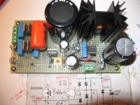
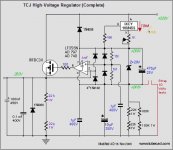
A nice new design from John Broskie:
http://www.tubecad.com/2006/11/blog0087.htm
I did build 2 of these for 250DC volts and 50mA load for my phono stage
Working real great!!
These can be called "regulations..."
I did use a LF356N as IC and 7mA in the IXCP 10M45 {could use a DN2470}
Ripple invisible at the scope... and no variation of output voltage between
0 and 300mA... done tests until 1.2A
regards.
Alain.
Attachments
A couple of nice articles here including a few on beginning PS design: http://www.audioxpress.com/resource/audioclass/index.htm
Nordic said:Why do they call it B+?
correct me if I am wrong, but doesn't B refer to a battery that used to run the plates in old portable Radios? B+ being the positive Terminal
Alain Dupont said:Bengali,
A nice new design from John Broskie:
http://www.tubecad.com/2006/11/blog0087.htm
I did build 2 of these for 250DC volts and 50mA load for my phono stage
Working real great!!
These can be called "regulations..."
I did use a LF356N as IC and 7mA in the IXCP 10M45 {could use a DN2470}
Ripple invisible at the scope... and no variation of output voltage between
0 and 300mA... done tests until 1.2A
regards.
Alain.
I like the Design, any chance I could sneak a peak at the schem?
")
thanks for all your replies. I did get the Valve Amp book. Been reading it over and over. I have trouble grasping some of concepts, how to derive the appropriate values for R,C,L's.
I cannot recall the exact values, but for example, in the book, it states like adding a 68uf resevoir cap to a 325V, the ripple will be 18v p-p, that is within the range. What is a good range?
There is a chart of showing attentuation depending on the stages of R-C's. Then he goes into talking about ripple current.
One of the replies was you have to know what your load is
to calculate the correct values. I'm working on an Aikido Line stage. Going to use the 6GC7 &6DJ8's.
So my load is 200V * 40mA(?)
I'm just trying to get a better understanding of how to
derive the appropriate values. The goal being to achieve a low ripple,noiseless, regulated pwr supply.
The amount of acceptable ripple depends on the circuit supplied- what's the level of signals, power supply rejection, desired signal-to-noise, and such. For example, a cascode first stage for a phono preamp will handle tiny signals and has low PSR, so a superbly low level of ripple is needed, microvolts or less. By contrast, a push-pull output stage will have huge signals and high PSR, so 18V of ripple might be just fine.
re the why is it called B+
afaik
before mains power was widely available, all valve/tube radios ran off batteries, generally there were three,
A, B and C.
A = accumulator, big lead acid jobs that were used for heater supplies, early tubes had 1.5v heaters, you would take these along to your local hardware store/ petrol station or similar, every so often to get them charged up.
B = hi tension, I've seen these in old valve radios, they were in the order of 90volts or so.
C = Bias batteries, used to bias the tubes to the correct point in the curves, virtually no current required,
the terms just stick around.
bill
alexmoose said:
correct me if I am wrong, but doesn't B refer to a battery that used to run the plates in old portable Radios? B+ being the positive Terminal
Yes. In the old days of radio, batteries were always used for power, and the batteries were named as follows:
A battery - Filament supply. Low voltage, high current
B battery - Plate supply. High voltage, low current
C battery - (optional) bias supply. Medium voltage, low current.
Reid
Bengali,
There is a good B+ supply for 250 Volts DC at 60 mA:
http://www.fortunecity.com/rivendell/xentar/1179/projects/toccata/Toccata.html
Just in the middle of the page...
A good example to start with !
Alain.
There is a good B+ supply for 250 Volts DC at 60 mA:
http://www.fortunecity.com/rivendell/xentar/1179/projects/toccata/Toccata.html
Just in the middle of the page...
A good example to start with !
Alain.
- Status
- This old topic is closed. If you want to reopen this topic, contact a moderator using the "Report Post" button.
- Home
- Amplifiers
- Tubes / Valves
- +B Power Supply Basics