This is a turntable but it seems to be a power supply issue so I'll try this subforum.
This turntable spun backwards, then I recapped it (since I read this is a common issue and old caps are at fault), now I can't get it to do anything. I checked my work multiple times and can't find any issue. Working through it with the voltmeter I found the +/- 15V power supply isn't working.
I'm a bit confused by the schematic, the emitter and collector of the regulators are in opposite positions from what I'm used to. Normally power goes in the collector, is controlled by the base, then the regulated voltage comes out the emitter.
In the schematic, the base and emitter of TR1 are both 24V, and the base and emitter of TR19 are both -24V. And there's no voltage on the collectors. I tried replacing TR1 and no change.
Can anyone help? A description of how the power supply circuit works would be helpful. I'm not sure how the power switch system works for this unit either. I'm a full time tech, but B&O never seems to give me good luck.
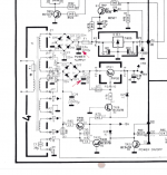
Full schematic available here.
Browse Beogram - Beogram 8002 manuals
This turntable spun backwards, then I recapped it (since I read this is a common issue and old caps are at fault), now I can't get it to do anything. I checked my work multiple times and can't find any issue. Working through it with the voltmeter I found the +/- 15V power supply isn't working.
I'm a bit confused by the schematic, the emitter and collector of the regulators are in opposite positions from what I'm used to. Normally power goes in the collector, is controlled by the base, then the regulated voltage comes out the emitter.
In the schematic, the base and emitter of TR1 are both 24V, and the base and emitter of TR19 are both -24V. And there's no voltage on the collectors. I tried replacing TR1 and no change.
Can anyone help? A description of how the power supply circuit works would be helpful. I'm not sure how the power switch system works for this unit either. I'm a full time tech, but B&O never seems to give me good luck.
Full schematic available here.
Browse Beogram - Beogram 8002 manuals
Attachments
> Normally power goes in the collector, is controlled by the base, then the regulated voltage comes out the emitter.
Yes, for a simple small regulator.
Here the big transistors are boosters for little transistors amplifying an error voltage. Yes, it is drawn confusing.
Regulated Power Supplies
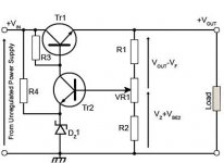
In the B&O, the -negative- regulator has the Zener and makes solid -15V. The +positive+ regulator will often "follow" the -reg with two equal resistors and a ground reference; however here there is a Zener and I am not sure just what is controlling the positive side.
+/-24V raw DC is reasonable input. Same B and E says the error amplifiers are dead. Note that TR21 seems to cut both-off both sides and might be the common fault.
EDIT: sorry, the example image I show is for collector-input. You can do the same thing emitter-input by backward-thinking. I'm sure B&O knew what they were doing.
Yes, for a simple small regulator.
Here the big transistors are boosters for little transistors amplifying an error voltage. Yes, it is drawn confusing.
Regulated Power Supplies
In the B&O, the -negative- regulator has the Zener and makes solid -15V. The +positive+ regulator will often "follow" the -reg with two equal resistors and a ground reference; however here there is a Zener and I am not sure just what is controlling the positive side.
+/-24V raw DC is reasonable input. Same B and E says the error amplifiers are dead. Note that TR21 seems to cut both-off both sides and might be the common fault.
EDIT: sorry, the example image I show is for collector-input. You can do the same thing emitter-input by backward-thinking. I'm sure B&O knew what they were doing.
Attachments
Last edited:
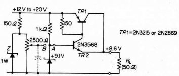
The emitter-input form is shockingly uncommon in simple regulators. It is more common as a wrapper around an IC chip, but that's confusing. Here's a simple one:
Three Transistor Voltage Regulator (CB986E)
(I have no idea why it says "Three Transistor..")
Rod shows a more complicated example:
LDO Regulators
Three Transistor Voltage Regulator (CB986E)
(I have no idea why it says "Three Transistor..")
Rod shows a more complicated example:
LDO Regulators
Attachments
+/-24V raw DC is reasonable input. Same B and E says the error amplifiers are dead. Note that TR21 seems to cut both-off both sides and might be the common fault.
.
I just tried disconnecting the collector of TR21 and that didn't do anything.
I noticed that if I put the ohm meter on the collector of TR20 right after unplugging the unit, the relay would click on for a moment and some voltage would come out of this circuit. I then replaced TR20 and TR19 and no change. I think that tells me something though?
Where are the error amplifiers in this circuit? What are TR18 and 20 doing with their bases grounded?
Last edited:
It's sort of a cascade. The +5V has to be present the get -15V and the -15V must be there in order to get +15V.
The power on/off with TR21 short circuit the +5V comming in via R83, no more minus15V and consequently no +15V.
Since opening TR21 made no difference, look at the presence of the +5V making the emitter TR20 +0V6.If so and no -15V, look at a shorted D26 (15V zener) or an open TR20,TR19 or R81.
An emitter-base short on TR19 is also possible.
Mona
Last edited:
> Here a simplified schematic.
Thanks. I started simplifying but fell asleep. I drew plus-up so I could understand.
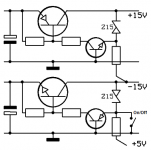
Grounded-base is a fine voltage amplifier. But no current gain. Low input impedance. It is rarely seen in audio. Here we can have *large* current in the Zener so the lack of current gain is not a problem. The grounded-base stage does not invert so it can save a few parts. And this configuration is "low dropout": if the raw supply sags to 16V it can still deliver 15V.
There is +5V from another supply through 560r to TR20 emitter. Its base is at 0V so about 8mA flows to TR20 and along to the pass transistor base, which turns it on. When the output voltage comes near 15V, the Zener conducts and steals current from TR20 emitter, thus pass transistor, and voltage falls. It will find a happy state where the pass transistor conducts just-enough to balance. If we assume Vbe is 0.6V and Vz=15V, it comes to 14.4V.
The positive regulator won't start until there are a few volts at "-15V" to force current through 1k2 to TR18. After that all the same, except backward.
TR21 can divert current from 560r and shut-off the negative reg, which kills the positive reg.
TR21 drive and collector may be critical if it is not coming-up. I can't see why TR21 could fail, but the computer should be toggling its base up or down and the collector should go down or up. You can short the base to ground to over-ride the computer and force ON. (There's a resistor will protect the computer from the short.) You can lift the collector leg of TR21 to force ON if TR21 has gone short.
Thanks. I started simplifying but fell asleep. I drew plus-up so I could understand.
....Where are the error amplifiers in this circuit? What are TR18 and 20 doing with their bases grounded?
Grounded-base is a fine voltage amplifier. But no current gain. Low input impedance. It is rarely seen in audio. Here we can have *large* current in the Zener so the lack of current gain is not a problem. The grounded-base stage does not invert so it can save a few parts. And this configuration is "low dropout": if the raw supply sags to 16V it can still deliver 15V.
There is +5V from another supply through 560r to TR20 emitter. Its base is at 0V so about 8mA flows to TR20 and along to the pass transistor base, which turns it on. When the output voltage comes near 15V, the Zener conducts and steals current from TR20 emitter, thus pass transistor, and voltage falls. It will find a happy state where the pass transistor conducts just-enough to balance. If we assume Vbe is 0.6V and Vz=15V, it comes to 14.4V.
The positive regulator won't start until there are a few volts at "-15V" to force current through 1k2 to TR18. After that all the same, except backward.
TR21 can divert current from 560r and shut-off the negative reg, which kills the positive reg.
TR21 drive and collector may be critical if it is not coming-up. I can't see why TR21 could fail, but the computer should be toggling its base up or down and the collector should go down or up. You can short the base to ground to over-ride the computer and force ON. (There's a resistor will protect the computer from the short.) You can lift the collector leg of TR21 to force ON if TR21 has gone short.
Attachments
To make a short story long ...> Here a simplified schematic.
Thanks. I started simplifying but fell asleep. I drew plus-up so I could understand.

Mona
There is +5V.
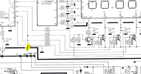
TR23 is shorting it to ground, its base is turned on. Disconnecting the collector gives me the +15V back.
This takes us away from the part of the circuit we've been discussing. Here's another clip of the schematic since TR23 isn't even in the first clipping. The link in my first post gives the full schematic.
I think TR6 needs to be on to turn TR23 off?
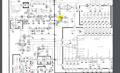
And this signal comes from NN which is on the other page of the schematic, in the second clipping. Anyone know what the thing I highlighted in that clipping is?
TR23 is shorting it to ground, its base is turned on. Disconnecting the collector gives me the +15V back.
This takes us away from the part of the circuit we've been discussing. Here's another clip of the schematic since TR23 isn't even in the first clipping. The link in my first post gives the full schematic.
I think TR6 needs to be on to turn TR23 off?
And this signal comes from NN which is on the other page of the schematic, in the second clipping. Anyone know what the thing I highlighted in that clipping is?
Attachments
Last edited:
TR21 is turned on now, it was turned on earlier too I think, then it wasn't turning on? So something isn't entirely consistent here.
When TR21 and 23 are disconnected the motor spins but way too fast, and the display doesn't light up. I've seen a couple display digits light up from time to time but not consistently.
When TR21 and 23 are disconnected the motor spins but way too fast, and the display doesn't light up. I've seen a couple display digits light up from time to time but not consistently.
It is probably a hoopless situation. I suppose the turntable is from the 80-th.I think the µC used is a OTP (One Time Programmable), is with the program memory in eprom without the window=not erasable.If i remember well, garantied memory of 10 years, long time overdue.
Not sure, the manual only name the µC R1093, never heart if it.A curious detail is that the power connection are not at the corner pins. The only one I now of is the Z80 but that's only a µP.
Mona
Not sure, the manual only name the µC R1093, never heart if it.A curious detail is that the power connection are not at the corner pins. The only one I now of is the Z80 but that's only a µP.
Mona
Probably not useful info at this point: Best guess would be shielding for that NN line. Looks like TR6 and friends are providing a sort of Watchdog for the uC. The line gets a pulse, probably every few milliseconds, when the uC is running normally. Then it could double as +/-15V control to turn the unit off, just by suspending those pulses.
Cheers,
Rick
Cheers,
Rick
- Home
- Amplifiers
- Power Supplies
- B&O Beogram 8002 Power Supply Issue