D201 is definately still behaving as a diode. I have not yet rechecked tr204 but I did check all the transistors every time I tryed powering it up and from a basic diode check it looked ok. I could take it out and do a hfe check but it seems unlikely that it would cause this fault unless it was SC or OC.
I plan to dig out my scope I have not used it for some time so I am not sure where it is but I know I still have it somewhere. It is nt fast but hopefully I should be able to see if it is oscillating. I will also wire ip a mains buib I have some 100w incandecent bulbs would these be suitable or does it need to be closer to the power of the amp?
Thanks,
Andy
I have checked the bias path and all the components measure correctly and are wired together correctly as far as I can tell.
Andy
Andy
The amp is from arround 1974 to 78 probably nearer 74. I would be very nterested to hear what your approach would be.
Thanks
Andy
1. You need to current limit the supply lines and the simple way is to take some blown
fuses and solder 100 ohm resistors across them and use those until you get things
ironed out. You MUST test the amp with no load on the output due to the current limiting.
2. Next, you need to take the bias network out of the picture. Solder a jumper wire
from the base of IC201 to the base of IC202.
3. You said in your first post that 201 and 202 were blown, I take it you mean TR not
the IC outputs. It is very difficult to blow those transistors and it suggests that
perhaps the input blocking cap is blown. The unit is so old that you should replace
every electrolytic cap and not proceed further until you do it.
4. Transistors can fail in such a way that they test OK with a diode test but their breakdown
voltage is degraded. I would pull the VAS TR203 and then jump the collector
to the B+ through a 1K resistor, does the output go to within a volt or two of the B+,
otherwise something is wrong. Connect the 1K to B- and similarly the output should go
to within a volt or two of B-. When you do these tests, no load on the output, measure
the drop across the 100 ohm resistors in the fuse lines, the drop across them should be
minimal even when you drive the output rail to rail. If it fails these then debug it.
Did you resistance check the .39 ohm emitter resistors on the outputs?
You will learn very quickly that you blow and waste new transistors unless you current
limit the supply lines, often multiple transistors at a time.
Last edited:
Many thanks for your guidance, when the amp blows is is taking ou the O/P devices so yes IC 102 and 202 are blowing and blew again in the last test. Tr201 and tr202 were blown when I revived the amplifier but have not failed again since I replaced them.
I did current limit the supply my mistake was not knowing when it was fixed as it appeard to be working just with the bias set very low. So I took them out it continued to work for a while then either due to me touching a component or as it heated up it failed again.
I did check to output resistors they both measure ok.
Thanks again for your help. I will report back when I have made the tests you suggest.
Regards,
Andrew
Next update, sorry PB2 realised I didn't understand your instructions when I looked at actually implementing them. Did you mean 1k to the + - power rails? I didnt understand the ref to b+ b-.
I have replaced blown tr3 and IC201 and 202, I also relaced 10R resistor R210 it still measured ok but was burnt.
Run up with resistors in rails I am using 150r as that what I have but I hope this doesnt make a dfference. Op bases are linked together. Its up and o/p it at 70mV so its not at a rail.
I measured zenner its correct at 9.1v.
I measured bottom of R203 this should be 23v it is actually at 31 so it looks like no current is flowing through the i/p stage. Any ideas why?
many thanks,
Andy
Ajusted O/P so 10mV accross o/ p resistors this was a tiny movement on pot the bias resistor is jumpered to 0r.
Measured base of tr207 this is listed as -30.1 I measure -8.7 and I noticed when I touch this point voltage accross the o/p resistors jumps up. This is what caused the failure when the limiting resistors were not in place.
I still dont know what it is.
Andy
Measured base of tr207 this is listed as -30.1 I measure -8.7 and I noticed when I touch this point voltage accross the o/p resistors jumps up. This is what caused the failure when the limiting resistors were not in place.
I still dont know what it is.
Andy
If it is of any help, I recently repaired a Beomaster 1900 (~1976 !) and I found most of the electrolytic capacitors were dead. I would suggest to check all of them.
It would be very interesting to know why the input transistors failed ... maybe at some point.
150 ohms is fine, what is the drop across them with the bias down?
Am I understanding that you took the jumper out and am able to bias the outputs?
I would back up if you did, and do the 1K tests first with the bias low.
connecting the 1K to the b+ and b- tests if the outputs can swing the full supply
without high leakage. Measure the voltage on the emitter resistors in each state.
You can ground the 1K to get roughly 0V out and probe voltages to see if they
make sense.
VERY interesting that you have problems when probing TR207, because it forms
a current source with TR206 and there has been discussion about how they can
oscillate and most will oscillate locally. Adding a base resistor cures this issue,
it is a very common oversight.
I was going to say first take some measurements but I notice voltages on the
schematic, but can't read them. What is the B- supply voltage? And what is it
at the other end of R216?
Subtract those and use I=V/R to compute the current source current by design
according to the schematic.
Connect the 1K resistor to ground so that the output is near zero volts.
Next lift the base wire of TR206 and wire a 4.7K resistors in series, this should
cure the oscillations.
Try measuring voltages again, do they make sense? You will not get the schematic
values if the 150R are dropping a lot of volts.
Hi,
It is biased with a jumper across the 330R R18 and just a small amount or resistance from R217 dialed in (I started with this set to 0R point).
O/P devices are new (again) so should not be faulty (yet).
I am back inside as shed is too cold again now but I will make further checks tomorrow or possibly later if I warm up.
Can I clarify that what you want me to do is connect a 1K resistor from collector of TR203 (TR203 removed) to positve rail (35V) and negative rail(-35v) as I still don't recognise the use of +B and -B it doesn't mean anything to me sorry.
I have attached a diagram with all the voltages I measured. I also checked the output with a scope (Only 2MHz but hopefully fast enough to see osc) and saw no oscillation just a bit of hum (>5mV). Not measured if TR207 is oscillating I can do that as well when I go back out.
C203 was S/C (now replaced) maybe this cause input TRs to fail.
Any further ideas with all the voltages from diagram?
It looks like something is very wrong around the TR206 and TR207. TR206 has been replaced but not TR207. TR207 measured correctly with a diode test compared to other channel.
Many thanks again,
Andy
Attachments
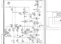
Supply voltage is +/- 31.5V
R216 is -30.3v (I think my diagram is not a very good quality scan) - actually I don't think this can be right it must be -30.9 as otherwise the transistor would be off.
The new diagram (last post) shows the voltages about as good as the scan I have does.
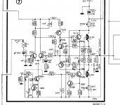
I have also attached a scan of the V2 amplifier (I don't have this mine is the old one) the voltages on this are a bit easier to read (But I am not sure if they are still valid) but it does show significant updates around this area - looks like your supposition that this could be unstable without base resistor was implemented!
R216 is -30.3v (I think my diagram is not a very good quality scan) - actually I don't think this can be right it must be -30.9 as otherwise the transistor would be off.
The new diagram (last post) shows the voltages about as good as the scan I have does.
I have also attached a scan of the V2 amplifier (I don't have this mine is the old one) the voltages on this are a bit easier to read (But I am not sure if they are still valid) but it does show significant updates around this area - looks like your supposition that this could be unstable without base resistor was implemented!
Attachments
9V in red is actual measured at this point. All of the red readings are actual measured.
Just went back out and TR207 is definitely unstable, it changes as the probe is attached so hard to say what is happening when not attached.
I tried adding a base stopper resistor to TR207 of 1K. This made the oscillation stable but did not remove it. In this configuration the oscillation is approx 10mV high ans 10mS peak to peak. The output current went up not down.
Andy.
B+ = pos rail
B- = neg rail
Just old terminology
Note that TR206 also has a 68 R in the emitter lead, this probably also helps stability.
I'm heading out but will look at the voltages later.
Right about the outputs being new, but lets hope you didn't get fakes,
the rail to rail thing just helps get some confidence that it is all working.
Fakes tend to have lower breakdown voltage so there is a chance it
might catch one, not likely at these low supply voltages.
I would get the current source working. Then we can concentrate on the bias
network.
9V in red is actual measured at this point. All of the red readings are actual measured.
Then the rail is not at -31.5 ?
Can you measure more points ?
Hi Pete,
Many thanks for your help, I fitted the 68R, its still oscillating. No noticable osc in output but the bias currect source is still oscillating.
I am thinking replace TR207 next unfortunately its a A06 and I dont have any so will have to order some.
Do you agree?
O/P devices came from Farnell so hopefully are real parts.
Thanks for your help, this is by far them most complex fix I have tried so far.
Regards,
Andy
If you really have -9 V which would indicate a very large drop across the 150 ohm then you have a problem. That would be 3.4W in the 150 ohm resistor did you use a 5 or 10W?
The resistors often go up in smoke if you use a 1/2 W and something goes wrong.
We can compute the design value for the current source:
31.5-30.8 = .7V/120 = 5.8 mA
Let me think about the oscillation a bit more.
The resistors often go up in smoke if you use a 1/2 W and something goes wrong.
We can compute the design value for the current source:
31.5-30.8 = .7V/120 = 5.8 mA
Let me think about the oscillation a bit more.
Checked the rail voltage is correct +\- 31.5v.
Regards,
Andy
Then TR206 is dead and R216 is surely not in good shape.
- Status
- Not open for further replies.
- Home
- Amplifiers
- Solid State
- B & O amplifier repair - cascade fail help!