B & O amplifier repair - Finnaly fixed thanks!
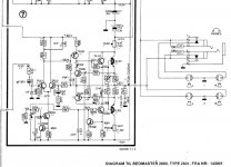
I am trying to repair a B and O amplifier in a 2801 receiver system. One amp works the other has a dead output driver. I managed to find a cct diagram and checked the other transistors. It looks like their has been some type of cascade failure. What I want help with is if I replace all of these is it likely to fix it or is there something else I should be checking for. (see diagram and list of blown parts below)
Failed transistors 201, 202, 203, 206, I.C 202
It looks like they modified this design post the circuit digram as Tr 209 and 210 are not present and it uses TIP 141,146 darlington parts for IC 201 and IC 202.
Any help gratefully received.
Andrew
Attachments
Last edited:
Replace the preset first. That causes all sorts of issues. Then replace what is required and DON"T use silly capacitors!
Many thanks, that is exactly the kind of thing I was after.
I had no plans to replace any of the capacitors they seem to be O.K.
Should I just replace the pre-set with an equivalent part or is there something more reliable?
Andy
I had no plans to replace any of the capacitors they seem to be O.K.
Should I just replace the pre-set with an equivalent part or is there something more reliable?
Andy
The Danish text at the bottom says "Schematic for Beomaster 2000. Type 2801. From S/N 143001", so yes there are different versions out there.
/U.
/U.
You may be able to clean the trimpot with some DeOxit FaderLube or similar. Replacing it is probably the better option, though. If it fails (wiper opens) you'll pop the output devices. You don't need anything special for the pot. If you can find one that fits the footprint, that's the best. Otherwise any pot of the same or similar resistance connected with very short leads will work too.
What you might be able to do is to replace the two fuses with 100 Ω resistors. That might allow the output devices to survive if the bias drives them to self-destruct. Once you have the circuit working, put the fuses back in.
I cut my teeth on A/V repair back in the mid 1980ies on a Beocenter 3500, by the way. 🙂
Tom
Many thanks. Thanks for the heads up on the schematic label. I will see what I can find in trimmers and replace it. I might even do the other channel at the same time.
I was going to use light bulbs instead of fuses but if 100R is the way to go I will use that approach.
Andrew
I was going to use light bulbs instead of fuses but if 100R is the way to go I will use that approach.
Andrew
All the transistors and two bourns 250R 500mW1 turn cermet trimmers are on order. Hopefully this will be enough to fix it. Thanks for your help.
Remove the blown transistors.
Then check every resistor for correct value.
Check unblown transistors for sensible diode function and CE open circuit.
Replace trimmer.
Fit new transistors.
Put mains lamp in series with amp and switch on.
Then check every resistor for correct value.
Check unblown transistors for sensible diode function and CE open circuit.
Replace trimmer.
Fit new transistors.
Put mains lamp in series with amp and switch on.
Thanks Nigel, I have already found one blown resistor, it was a 10r but was o/c. I have also found the right circuit diagram as it became clear the one I had dudn't match the design very well at all. Many of the ref numbers were wrong.
Will check all the rest now I have a cct to check them off against.
Andrew
Will check all the rest now I have a cct to check them off against.
Andrew
OK - I checked all the resistors, all the diodes and replaced all the faulty transistors and the OC 10R resistor. I replaced the trimmer and set it to100R the same as the other channel. I fitted light bulbs in both rails and the feed for the input stage.
I rechecked the transistors against the other channel to make sure they looked the same.
When I turned it on one of the PSU rail bulbs was very bright, so I turned it off immediately, unfortunately the O/P IC202 had already failed. It looks like too much current was coming in the base as the base collector is OK but base emitter is S/C. It appears I was fast enough that none of the other transistors appear damaged.
I am stumped I only have one more O/P device, and ideas what I should look for?
Andy
Clamp the base IC201 and IC202 together. If everything will remain the same, blame IC201 and IC202. If the current is reduced, fault R218 R219.
Next update. Some progress but no solution.
I found the feedback capacitor to ground was short, well about 70R. I replaced this and the O/P devices. I ran it up on 100R resistors, the bias current was still measuring very high. I shorted the bias resistor out and set the trim to 0R.
This enabled me to power it up. I set bias for 10mV accross o/p resistor this required hardly any increase in the pot it seemed far to sensitive. It seemed to have settled so I removed 100R resistors. I had to adjust bias down again but it could be set to 10mV. I noticed that the voltage accross the two output resistors was not the same 10mV on the positive rail and 14mV on the negative this difference was not present on the good amp. The output was sitting at 23mV so seemed OK for offset.
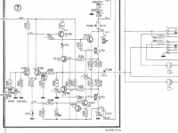
I was in the process of measuring the voltage on the temperature compensation cirucit you can see it shows 30v (probably its hard to read). The instant I touched R216 resistor with a probe the 100R input stage feed resistor started to burn the fuse on the positive rail blew and both the output devices blew and tr203 blew. I checked the meter it was set to volts so should have been high impedance. The other transistors seem ok. see digram below for tr203 its not the same as first diagram.
My supposition is it went unstable. Its possible it was slighty unstable before I touched this point, could this cause the increased bias sensitivity?
I have more O/P devices and a replacement for tr203 but there does not seem much point continuing till I have some idea of what to do next?
What might make it unstable?
What could have caused the massive increase in bias sensitivity?
Anything else I should check for?
I am using TIP 142 and 147 to replace the original TIP 141 and 146 parts due to availability, but as far as I can see they are identical except for their max volage specification and the new parts are higher.
Andy
I found the feedback capacitor to ground was short, well about 70R. I replaced this and the O/P devices. I ran it up on 100R resistors, the bias current was still measuring very high. I shorted the bias resistor out and set the trim to 0R.
This enabled me to power it up. I set bias for 10mV accross o/p resistor this required hardly any increase in the pot it seemed far to sensitive. It seemed to have settled so I removed 100R resistors. I had to adjust bias down again but it could be set to 10mV. I noticed that the voltage accross the two output resistors was not the same 10mV on the positive rail and 14mV on the negative this difference was not present on the good amp. The output was sitting at 23mV so seemed OK for offset.
I was in the process of measuring the voltage on the temperature compensation cirucit you can see it shows 30v (probably its hard to read). The instant I touched R216 resistor with a probe the 100R input stage feed resistor started to burn the fuse on the positive rail blew and both the output devices blew and tr203 blew. I checked the meter it was set to volts so should have been high impedance. The other transistors seem ok. see digram below for tr203 its not the same as first diagram.
My supposition is it went unstable. Its possible it was slighty unstable before I touched this point, could this cause the increased bias sensitivity?
I have more O/P devices and a replacement for tr203 but there does not seem much point continuing till I have some idea of what to do next?
What might make it unstable?
What could have caused the massive increase in bias sensitivity?
Anything else I should check for?
I am using TIP 142 and 147 to replace the original TIP 141 and 146 parts due to availability, but as far as I can see they are identical except for their max volage specification and the new parts are higher.
Andy
Attachments
Last edited:
Check the soldering of R216 .
TR201 and 2 were initially faulty did 9.1V? zener D201 survive .
Recheck TR204 could be supplying the bias imbalance .
TR201 and 2 were initially faulty did 9.1V? zener D201 survive .
Recheck TR204 could be supplying the bias imbalance .
Many thanks for the ideas, I will work through them and report back. I will recheck zenner but it measured OK as a forward diode.
Andy
Andy
When I turned it on one of the PSU rail bulbs was very bright, so I turned it off immediately,
Andy
You need to put a lamp in series with the mains not after the power supply.
This should limit current enough to stop blowing up components.
Clearly you have missed a fault somewhere if its still blowing up.
The trimmer needs setting to minimum bias current to start with.
- Status
- Not open for further replies.
- Home
- Amplifiers
- Solid State
- B & O amplifier repair - cascade fail help!