Hi Alex,
Nelson's article should do the trick. But as a rule of thump: match the MOSFETs based on date production codes. They typically don't drift that much. Also: they are somewhat self-balancing thanks to their negative temperature coefficiency. (as they get warmer, they draw less current).
Now, there IS another trick:
1) solder in 3 helper wires for just one of the MOSFETs on each side P and N (6 in all)
2) Now start with just one P and one N MOSFET soldered on to the helper wires. We now have a working amp - but only with one pair of MOSFETs...
3) Don't worry. - We are not going to draw any current: so no input signal connected nor any speaker output.
4) Connect an ammeter capable of 200 mA in series with the B+ rail between the power caps and the main board. Typically across where the fuse would normally be.
5) Turn on the amp.
6) Set the BIAS current to 110mA.
7) Turn off the amp.
8) De-solder only the 2SK1529 and mark that with 110 with a marker.
9) Now solder in the next 2SK1529.
10) Turn on the amp.
11) Ready the current draw across the meter. Let's say it reads 115mA.
12) Mark that 2SK1529 with the observed current draw - in this case 115mA.
13) Repeat for all the 2SK1529's you have.
14) Leave in the last 2SK1529 and set the BIAS to 110mA again if needed.
15) Now move the ammeter to the B- rail and reinsert the fuse for B+.
16) Turn amp off.
18) Remove the 2SJ200 and mark it 110.
19) Solder in the next 2SJ200.
20) Leave the BIAS setting where it is and note the current draw.
21) Turn off the amp. De-solder the 2SJ200 and mark it with the observed current draw. Let's say this one showed 105mA.
22) Repeat for all the 2SJ200's you have.
You now have a stack of MOSFETs marked with the actual current draw in the actual circuit. Now sort them as best you can so that each channel has 3 N-channel close to the same and 3 P-channel close as well. They do not have to be the same between N & P - just the same across P's and N's.
Now you are ready for the final assembly. Remove the helper wires - as they were only there to make it easy to solder in the MOSFETs during testing - without overworking your PCB traces.
Mount the grouped P's and N's. Apply thermal grease and micas. When everything is back to original mounted condition, connect the ammeter across the B+ fuse holder for each channel and set final BIAS and offset. BIAS rule of thumb is 110mA per pair. So 3 pairs should be ~330-340 mA. Offset should be <10mV after the amp is warm.
Good luck.
D.
AND, Success!!!
D (vilfort) thanks so much for your invaluable help, I wouldn't have done this without your help, YOU ROCK!!!
I will connect it and listen to it tonight...
Thanks again!
Alex
D (vilfort) thanks so much for your invaluable help, I wouldn't have done this without your help, YOU ROCK!!!
I will connect it and listen to it tonight...
Thanks again!
Alex
Thank you for the kind words, Alex!
I am happy to hear you got your amp up and running again. Happy listening!
D.
I am happy to hear you got your amp up and running again. Happy listening!
D.
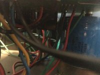
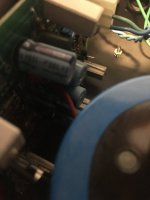
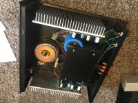
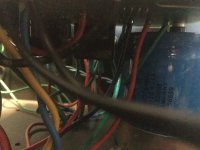
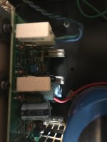
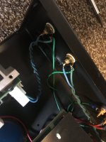
Here is mine, what else can I replace besides the capacitors ?
Attachments
to answer the earlier questions in case someone else asks later:
those Toshiba 2SK405 / 2SJ115 are definately vertical MOSFETs, not lateral MOSFETs like the ubiquitos Hitachis (and later Renesas and others). As has been pointed out, they are not directly interchangeable and the pinout is different.
Those Toshibas were later replaced by parts in the 2SK1530 / 2SJ201 family and could be used as replacements, but be careful....
The Toshibas were available in 2 different VGS (off) grades. So, you would want your pairs to have the same grade and if you hand to repair/replace any, you would want your replacements to have the same grade unless you understand how to adjust your circuit to compensate for different VGS (off) !
This is mostly a moot point now because all of these Toshiba audio MOSFETs have been discontinued for several years.
So, if you decide to buy any, test them carefully to verify you actually have what you think unless the seller gives you warm fuzzies that they are legit.
Caveat Emptor!!!
But, if you happen to find some that are good, be happy and use them wisely. They are some of the best MOSFETs ever made for audio with suprisingly good matching between N and P types. They truly "don't make 'em like that anymore" ...
Considering that the 2SK405 and the 2SK1530 are vertical mosfets, there is a good chance the outputs will experience thermal runaway with only a trimpot.
Normally, this simple biasing is only used with lateral fets (2SK1058/2SJ162).
It's also odd that the outputs have no Zobel. Not many amps are stable without it.
BTW, the IRFP240/9240 have the same pin-outs as the 2SK1530.
You can use them in place of the 2SK405 but the biasing network must be modified.

Yes! I have never really trusted B&K amps for that very reason.
"Considering that the 2SK405 and the 2SK1530 are vertical mosfets, there is a good chance the outputs will experience thermal runaway with only a trimpot.
Normally, this simple biasing is only used with lateral fets (2SK1058/2SJ162)."
"Considering that the 2SK405 and the 2SK1530 are vertical mosfets, there is a good chance the outputs will experience thermal runaway with only a trimpot.
Normally, this simple biasing is only used with lateral fets (2SK1058/2SJ162)."
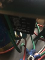
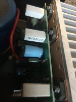
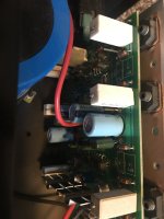
@SirPaulGerman: The pics you shared appear to be using 2SK1058/2SJ162s. Not much to fix on that amp if it is running... Sure, you can re-cap, but it may not yield a great deal unless you know the caps are out of spec.
What is wrong with the amp?
BTW: you can use Exicons here if you need to replace output MOSFETs: http://www.exicon.info/PDFs/ecx10n20.pdf and http://www.exicon.info/PDFs/ecx10p20.pdf - they are pin-compatible with the Hitachi's
What is wrong with the amp?
BTW: you can use Exicons here if you need to replace output MOSFETs: http://www.exicon.info/PDFs/ecx10n20.pdf and http://www.exicon.info/PDFs/ecx10p20.pdf - they are pin-compatible with the Hitachi's
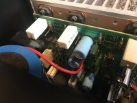
Well the amp is around 30 years old, anything I can replace beside the capacitors ?
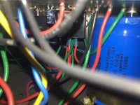
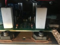
and those dale resistors sandstone, is there anything better for replacement ?
and those dale resistors sandstone, is there anything better for replacement ?
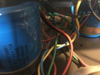
Sure - you can go nuts replacing things. So OK: New big can caps. And new 100uF-100V caps on each board. The wirewound sand cast resistors are fine - unless they are fried open. They have such low resistance .47ohm so 3 in parallel is only .157 ohm. Doubt you will hear any diffrence is you replaced them with non-inductive WW. But sure, have fun. Be sure to measure resistors. If they have not drifted or ar open, there is little need to upgrade those. The cost of say Vishay naked resistors is prohibitive 🙂. https://www.digikey.com/en/products...sIYXOoTY183t0LBlgV6ci7E20DA5K43AaAiNVEALw_wcB
so pretty much caps and power caps
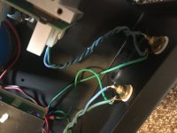
are they capacitors on the side board, are those in the signal path? therefore I need audio quality caps
are they capacitors on the side board, are those in the signal path? therefore I need audio quality caps
Here is a schematic:

C2 should be upgraded to audio quality.
Same is true for C1.
Both are in the signal path.
Good luck.
C2 should be upgraded to audio quality.
Same is true for C1.
Both are in the signal path.
Good luck.
Yes. The two caps C1 and C2 are directly in the signal path. The other C6, C7, C12, C13 are helping to stabilize voltages. So - sure - you may want to replace these 100uF - 100V caps if dried out. It all helps.
TBH - I have repaired 8-10 of these amplifier channels, different models, but same schematic with either 2, 3 or 5 pair of laterals. I have pulled almost every Capacitor and transistor off multiple boards and only had 1-2 Caps that have been more than 5% out of spec. Those C1 and C2 are high quality from B&K and I have never seen one out of spec myself. I have actually taken a completely torched 5-pr board and recycled all the caps to reuse on a DIY amp build because they tested perfect both uF and ESR. Been using that amp daily for over 2 years, without a problem.
YMMV - and of course it's DIY, sooooooo if you want to do it, just do it. If it sounds worse, you will just get more practice having to put the OEM stuff back in.
YMMV - and of course it's DIY, sooooooo if you want to do it, just do it. If it sounds worse, you will just get more practice having to put the OEM stuff back in.
Great advise! - What sounds good to one person may not be the other person's cup of tea.
About film caps: yes, C1 and C2. Not worth the trouble elsewhere. And the power caps are already bypassed.
Bob Cordell adviced at Burning Amp a few years back, that caps in the signal path (C1 and C2) should ALWAYS be of high quality. Without going nuts. He recommended Solen back then. But today there are many more to chose from. Some folks like Mundorf. Some like Clarity Caps.
Good luck.
If you replace all the caps with film, the amp should last forever ?
The only thing to worry are the power capacitors electrolytes
The only thing to worry are the power capacitors electrolytes
Two things - replacing electrolytic with film will be expensive and also hard to fit them on the board(s) and look close to factory/original. I assure you the power Caps are just fine and will surpass original spec.
It sounds like you are asking for confirmation and you might get that from someone, just not me.
I’m a purist and think these are well made amps to start with (albeit fairly simple and older design) that works/sounds very good. They are built like a tank and can survive almost anything you throw at them (you can kill it with abuse).
So go for it - make a list of the parts you need and do the full film conversion. Then come back after a month and tell us if you think it is worth the effort and cost. It’s DIY, take it to the bleeding edge and you will have a great tale to tell!
- Home
- Amplifiers
- Solid State
- B&K ST-202 Repair