Apparently, service info, including schematics and specs for bias adj., for B&K amps can be difficult, if not impossible, to locate. And yet, here I am trying. . . .
Looking for anything on the B&K 3220 three-channel amp. (Well, anything but the owner's manual.)
Thanks in advance.
Looking for anything on the B&K 3220 three-channel amp. (Well, anything but the owner's manual.)
Thanks in advance.
B&K --the original manufacturer packed up in 2010 .
Schematics ( if any ) are said to be available at Amplifier Technologies .
ATI Amplifier Technologies
I wouldn't hold your breath though.
No I didn't find a schematic either.
Schematics ( if any ) are said to be available at Amplifier Technologies .
ATI Amplifier Technologies
I wouldn't hold your breath though.
No I didn't find a schematic either.
Yep, I know the unfortunate B&K back story. And had already reached out to ATI, with little expectation of success (no word yet).
Its a mosfet amp isn't it ?
It also says -discrete circuitry so its not processor or digitally controlled so it should be not too hard to "reverse engineer " it -aka - tracing the circuit and writing down your findings .
Even if I didn't have a schematic it didn't stop me repairing most analogue amplifiers /test gear etc just logical-practical old school circuit tracing.
Blown output devices/overheating resistors /faulty capacitors /even HR soldered connections and a multitude more it just took a bit of determination to find the fault made easier using quality test gear.
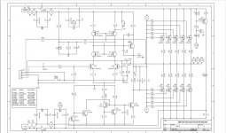
Ok, looks like I may have had some success. It appears that the file in the HiFiEngine library listed under "BK Components Reference 200.3" contains the same amp board schematic as was used in the Reference 3320 (even the face plate looks the same in the B&W photo). The PCB board number and Revision match, as do the few component values and locations that I checked. The schematic shows more output transistors than in the 3320, but that's because this circuit was also used in other, higher power B&K amps.
Attachments
Not too hard a circuit to trace Dbxdx5 --good detective work !
Your right just a difference (generally ) in the number of output devices.
Your right just a difference (generally ) in the number of output devices.
Thanks duncan2.
Re the bias for this amp, the B&K recommendation was to measure the DC current at the negative rail (after warming up) and set as follows:
4. Set bias of the amplifier by adjusting the bias pot (P2) mounted on the solder side of the board to achieve a reading of 200 mA on each channel for models ST 140, ST 140M, ST 202, and ST 202+. The bias for the Pro 600, EX 442 and M 200 amplifiers is 250 mA. Setting the bias higher than stated only causes the amplifier to run hotter and burn out faster. It does nothing for the sound quality of the amplifier.
I'm thinking 250mA is what I should aim for with the 3220, assuming it even needs adjustment. Thoughts?
Looking at the advertising of the amplifier the power supply is built overspec. and ( according to them ) stand up to some abuse .
I know the output mosfets very well as I used them ( at the time ) in several JLH designs and a class A of my own design .
Those TO3 devices will stand well over 250ma , I have personally run them well over that so 250ma is not a big deal -- "burn out faster " --who said that ?
If it was an unstable circuit that had HF oscillation-possibly but I have had the same active devices blackened with heat and they still worked while working on a circuit.
Apparently, service info, including schematics and specs for bias adj., for B&K amps can be difficult, if not impossible, to locate. And yet, here I am trying. . . .
Looking for anything on the B&K 3220 three-channel amp. (Well, anything but the owner's manual.)
Thanks in advance.
BK Components – Audio-Circuit [.dk]
Looking at the advertising of the amplifier the power supply is built overspec. and ( according to them ) stand up to some abuse .
I know the output mosfets very well as I used them ( at the time ) in several JLH designs and a class A of my own design .
Those TO3 devices will stand well over 250ma , I have personally run them well over that so 250ma is not a big deal -- "burn out faster " --who said that ?
If it was an unstable circuit that had HF oscillation-possibly but I have had the same active devices blackened with heat and they still worked while working on a circuit.
Ok, good to know, especially given your experience with these outputs.
I just checked the bias as it was presently set, and the channels were at 210mA, 178mA, and 175mA. Who knows what it was set at when it left the factory, but perhaps 200mA. I'll adjust to 250mA and move on with it.
Missed this yesterday. Thanks Worldie!
Follow-up question for duncan2 or anyone else who cares to weigh in. The B&K instructions for the bias procedure state that the setting should be carried out with an 8 ohm load and while inputting a 100mV 20kHz signal:
Any opinions on this?
The following procedure is for setting the bias and DC in the B&K amplifiers. Read the complete
procedure first. These procedures should be performed by a qualified technician.
1. Plug the amplifier into a variac. Monitor the (-) negative rail of each channel by removing
the fuse and placing a current meter across the fuse clips.
2. Connect an 8 Ω load to each channel. Supply an input signal of 100 mV RMS @ 20 Khz.
3. Slowly turn the variac up to operating voltage while monitoring the rails for excessive
current draw. The meters should not read more than 400 mA DC. If one or both read
more than 400 mA, turn the bias pots (P2) to minimum and retry.
4. Set bias of the amplifier by adjusting the bias pot (P2) mounted on the solder side of the
board to achieve a reading of 200 mA on each channel for models ST 140, ST 140M,
ST 202, and ST 202+. The bias for the Pro 600, EX 442 and M 200 amplifiers is 250 mA.
Setting the bias higher than stated only causes the amplifier to run hotter and burn out
faster. It does nothing for the sound quality of the amplifier.
5. Set the DC out of the amplifier by monitoring across the outputs. Adjust the DC pot (P1)
for 0 VDC ± 5 mVDC.
This is how I set the bias for the amp under discussion, but then I ran across an old thread where djk (R.I.P.) said not to use a load or signal.
B&K ST-2140 bias setting procedure?
Any opinions on this?
Look Dbxdx5 what I can say to you is that B&K obviously use different methods of setting the bias to their design than I do.
Its possible they were influenced by D.Self who again in articles "tore apart " anybody differing fronm his opinion in EW .
He was against a high bias setting and argued --well practically "dictated " that only a small amount of bias should be used ,part of his argument was the "Crossover Region " and he went into great detail to "prove " his point .
I know he has many followers but so does the now deceased ( RIP ) JLH.
As I sway towards JLH I will put what I do -
The bias is set to a predetermined amount consistent with a power amplifier being run in Class A before it changes over ,this can be a few watts or more depending on the setting .
This was D.Self,s "big problem " --the changeover it was not mine nor JLH,s and John was "shot down " by him ---as usual .
Its all down to listening quality ,in the UK 100,s of watts are ( normally ) not used much of the listening is done using a small number of watts and yes -scroll through EW and you will find JLH saying those exact words .
Now not all power amplifiers are designed to a certain known standard and if B&K say it must be set this way I leave their instructions to them.
What you describe is setting distortion levels using an 8 ohm resistor as a load while inputting an audio frequency sine wave signal .
This is how I test an amplifier for distortion / FR and especially STABILITY while ( old school coming now ) connected to a THD distortion meter tester .
Sure I know its old school replaced with virtual apps and digital software stuff but It works for me.
I have no intention of being dragged into another long drawn out argument ,went through that many decades ago ,if others have opposite views --fair enough but what I went on after seeing much less than 1mv of noise and low distortion /IM/ speed during changes in signal -yes there are a lot of tests but if you get it to a level you can live with and it ---Sounds Good -IE - natural then that to me is more important --to my ears.
Everything is clear - if you do more than necessary, the amplifier will burn out. Maybe not right away 🙂
Look Dbxdx5 what I can say to you is that B&K obviously use different methods of setting the bias to their design than I do.
Its possible they were influenced by D.Self who again in articles "tore apart " anybody differing fronm his opinion in EW .
He was against a high bias setting and argued --well practically "dictated " that only a small amount of bias should be used ,part of his argument was the "Crossover Region " and he went into great detail to "prove " his point .
I know he has many followers but so does the now deceased ( RIP ) JLH.
As I sway towards JLH I will put what I do -
The bias is set to a predetermined amount consistent with a power amplifier being run in Class A before it changes over ,this can be a few watts or more depending on the setting .
This was D.Self,s "big problem " --the changeover it was not mine nor JLH,s and John was "shot down " by him ---as usual .
Its all down to listening quality ,in the UK 100,s of watts are ( normally ) not used much of the listening is done using a small number of watts and yes -scroll through EW and you will find JLH saying those exact words .
Now not all power amplifiers are designed to a certain known standard and if B&K say it must be set this way I leave their instructions to them.
What you describe is setting distortion levels using an 8 ohm resistor as a load while inputting an audio frequency sine wave signal .
This is how I test an amplifier for distortion / FR and especially STABILITY while ( old school coming now ) connected to a THD distortion meter tester .
Sure I know its old school replaced with virtual apps and digital software stuff but It works for me.
I have no intention of being dragged into another long drawn out argument ,went through that many decades ago ,if others have opposite views --fair enough but what I went on after seeing much less than 1mv of noise and low distortion /IM/ speed during changes in signal -yes there are a lot of tests but if you get it to a level you can live with and it ---Sounds Good -IE - natural then that to me is more important --to my ears.
Appreciate the background and perspective. No intention to stir things up!
- Home
- Amplifiers
- Solid State
- B&K Reference 3220 Amp: Schematics Needed