Hi everyone,
I just finished putting together my first point-to-point diy tube amp yesterday and I can't get any sound out of the speaker. No hiss no buzz. The speaker works and is wired up correctly. All the tubes are lit and the fuse is not blown. Checked through all the connections and I can't find any wrong or shorted connections. The only thing that I have found so far is that the voltage at B+ is 0vdc regardless of if it is Standby/On/Off. I attached a picture and the schematic below. The voltage before the rectifier diodes is 220vac when T1 or T2 are tested to the ground and when T1 and T2 are tested in relation to each other they read 240ac. So the PT is working. Did I connect the diodes wrong or could it be possible that there is a mistake in the schematic? Also when the amp is turned off B+ to the ground is 470k ohms. That means I don't have any shorts, right?
Thanks
Attachments
So the PT is working. Did I connect the diodes wrong or could it be possible that there is a mistake in the schematic?
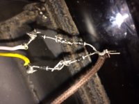
That's the problem. Is the HV secondary winding's center tap grounded? BTW, that wiring doesn't look safe.
Last edited:
Thanks for responding. You are right. I forgot that I had purchased a different pt because the one in the schematic was discontinued(it had the same voltage specs). The one that I bought does not have a center tap. It has a static shield instead which I connected to the ground. So, I guess I should contact the company and see if they have any that have the center tap.
P.S. The wiring is definitely not safe. I took of the rubber tubing off to test it.
Thanks
P.S. The wiring is definitely not safe. I took of the rubber tubing off to test it.
Thanks
With due respect: ouch!!!!!!!!!!!!!!!!
Parts are soldered or twisted before soldering, what's that shoelace type knot joining diodes?
Why are parts floating unsupported?
Please post a picture of the entire amp guts, I fear it's absolutely unsafe and shouldn't even be plugged into the mains.
Sorry.
Parts are soldered or twisted before soldering, what's that shoelace type knot joining diodes?
Why are parts floating unsupported?
Please post a picture of the entire amp guts, I fear it's absolutely unsafe and shouldn't even be plugged into the mains.
Sorry.
Point to point wiring doesn't mean junctions floating in mid air, even with insulating tubing. An experienced constructor might use a few of these in the small signal circuitry if he runs out of tags, but never in the PSU. One rule to follow is that a joint should never rely on solder for mechanical strength, just for electrical conductivity.
I should contact the company and see if they have any that have the center tap.
You might be able to use the transformer that you have, if the rated secondary rms voltage x 1.414 is usable.
This would result from a full wave bridge rectifier, which is four diodes instead of 2 (counting series diodes as just one).
No center tap is needed for this connection.
Last edited:
- Status
- Not open for further replies.