Cant find any useful links right now but they were small daughter boards with (I'm assuming) matched transistors etc. on them. The term hybrid chip might be my words 🙂. A member here redid them in surface mount as they became extinct.
Yes I think it's pretty good for a 50W amp.[ amazing slew rate & bandwidth ]
Oh, like a thick / thin film module or something I guess? I vaguely remember that kind of technology from the 70s.they were small daughter boards with (I'm assuming) matched transistors etc. on them.
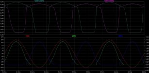
I had a quick play with it, but sadly I can't recreate the quite good class AB behaviour that I saw in earlier incarnations. What seems to happen now, is because the MOSFETs turn off completely, the Vgs drops to zero (actually about -0.5V), and takes a while to come up again for the next conduction cycle, so it's quite glitchy. Of course that's one of the advantages of NS designs, is the MOSFETS never actually turn off. The output still looks fine visually, but distortion is 0.000162%, i.e. about 15x worse.One interesting side-effect of this design is that by adjusting bias levels (R23,R24,R36,R37) you can make it run in class B, AB or class A too. I haven't really explored those modes but I will and I'll post back some results.
In the attached image, the top trace shows the Vgs of the MOSFETs. In the lower trace you can see the glitchy currents and the still good-looking output.
Attachments
Yes, but might have just been on a PCB. can't remember. Keep up the amazing work on this thread. I for one am happy to see non switch designs on DIY audio. Particularly with MOSFETS.like a thick / thin film module
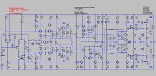
You've sent me down a rabbit hole... I'm playing around with adapting the BEANS amp so it's just a regular class-B amp. So the front-end is the same, and the novel MOSFET drive is retained with the crazy totem-pole (I'm gonna call it the "flying base" topology), but putting a normal class-B bias for it. Hopefully it'll perform worse than the BEANS amp or else I've just wasted months of my life haha.
Well I think testing it against a class-B design is a good reality check, so thanks for prompting me to do that...
Class-B comparison
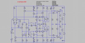
So I tried to make a class_B amp using my "flying base" topology but it didn't work well. It has the same problem of the gate voltages crashing to zero. So I ditched that output configuration and just made a standard class-B output driven by the BEANS front-end.
So I tried to make a class_B amp using my "flying base" topology but it didn't work well. It has the same problem of the gate voltages crashing to zero. So I ditched that output configuration and just made a standard class-B output driven by the BEANS front-end.
Attachments
I adjusted the quiescent current for minimum distortion at 1V, 1kHz input (25W out into 8ohms), then ran a bunch of simulations to compare to the BEANS amp.
Quiescent current was 199.3mA with bias spread resistor @ 845 ohms.
Then I adjusted the Cdoms. 75pF and 150pF looked good, and gave this AC analysis:
Closed loop gain -3dB 1.15MHz with a 0.15dB lift @ 346kHz
Open loop gain 139dB, P1 @ 1.84Hz
Phase margin 64.3° Gain margin 16.8dB
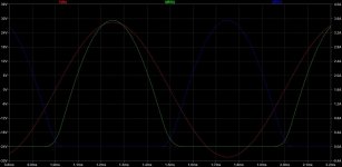
Then I checked stability with a square wave, 10kHz, 1V, 10nS rise/fall.
Square wave performance was very pretty, 24V/uS slew rate.
Output impedance: 720uohm @ 1kHz, 14.3 mohm @20kHz
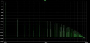
I did a spot-check of some distortion levels:
1kHz 0.1V 8R Total Harmonic Distortion: 0.000219%
1kHz 0.2V 8R Total Harmonic Distortion: 0.000219%
1kHz 0.4V 8R Total Harmonic Distortion: 0.000650%
1kHz 1V 8R Total Harmonic Distortion: 0.000556%
1kHz 1.42V 8R Total Harmonic Distortion: 0.000901%
1kHz 1.42V 4R Total Harmonic Distortion: 0.001423%
20kHz 0.2V 8R Total Harmonic Distortion: 0.010556%
20kHz 1V 8R Total Harmonic Distortion: 0.013414%
20kHz 1.42V 8R Total Harmonic Distortion: 0.073952%
20kHz 1.42V 4R Total Harmonic Distortion: 0.106307%
Quiescent current was 199.3mA with bias spread resistor @ 845 ohms.
Then I adjusted the Cdoms. 75pF and 150pF looked good, and gave this AC analysis:
Closed loop gain -3dB 1.15MHz with a 0.15dB lift @ 346kHz
Open loop gain 139dB, P1 @ 1.84Hz
Phase margin 64.3° Gain margin 16.8dB
Then I checked stability with a square wave, 10kHz, 1V, 10nS rise/fall.
Square wave performance was very pretty, 24V/uS slew rate.
Output impedance: 720uohm @ 1kHz, 14.3 mohm @20kHz
I did a spot-check of some distortion levels:
1kHz 0.1V 8R Total Harmonic Distortion: 0.000219%
1kHz 0.2V 8R Total Harmonic Distortion: 0.000219%
1kHz 0.4V 8R Total Harmonic Distortion: 0.000650%
1kHz 1V 8R Total Harmonic Distortion: 0.000556%
1kHz 1.42V 8R Total Harmonic Distortion: 0.000901%
1kHz 1.42V 4R Total Harmonic Distortion: 0.001423%
20kHz 0.2V 8R Total Harmonic Distortion: 0.010556%
20kHz 1V 8R Total Harmonic Distortion: 0.013414%
20kHz 1.42V 8R Total Harmonic Distortion: 0.073952%
20kHz 1.42V 4R Total Harmonic Distortion: 0.106307%
Last edited:
Here's a comparison of BEANS with Class-B
BEANS Class-B Iq 283mA 199mA-3dB 3MHz 1.15MHzOLG 143.9dB 139dBPhase Margin 64.7° 64.3°Gain Margin 13.0dB 16.8dBSlew rate 60V/uS 24V/uSOutput Z 1kHz 611u ohm 720u ohmOutput Z 20kHz 1.19m ohm 14.3m ohm Distortion: BEANS Class-B BEANS advantage THD 1kHz 0.1V 8R 0.000002% 0.000219% 110x betterTHD 1kHz 0.2V 8R 0.000006% 0.000219% 37x betterTHD 1kHz 0.4V 8R 0.000010% 0.000650% 65x betterTHD 1kHz 1V 8R 0.000011% 0.000556% 51x betterTHD 1kHz 1.42V 8R 0.000012% 0.000901% 75x betterTHD 1kHz 1.42V 4R 0.000013% 0.001423% 110x betterTHD 20kHz 0.2V 8R 0.000161% 0.010556% 66x betterTHD 20kHz 1V 8R 0.000733% 0.013414% 18x betterTHD 20kHz 1.42V 8R 0.001711% 0.073952% 43x betterTHD 20kHz 1.42V 4R 0.003051% 0.106307% 35x better
Last edited:

Interesting work. Aren't you planning to build?
I can relate to you. I enjoy simulating complex circuits and going deep into how the circuit operates, and especially looking for something novel/different. I have a few designs that I put many hours on, that I will definitelly build and test, in fact I'm working on it.
Now the interesting reflection (at least for me it's interesting). I am able to enjoy music on very simple equipment. In fact I had a reality check recently: a receiver from the seventies surprised me in the most unexpected way. I bought it to repair and gift to a friend (he's now very happy with the thing and his Philips belt drive turntable, also a nice unit from the seventies). I was delighted with the music it produces. MUSICAL. Not a precise and transparent piece of electronics. But the stimulation you get from the music is a very nice thing and it gave it to me abundantly! Having looked at the schematics before listening I was biased against this outcome. It has very simple single transistor stages in the preamp, some electrolytic coupling caps, quasi topology power amp with RCA 2N3055 (single supply and output electrolytic).
About your recent posts (class AB / class B), I would say it's probably worth driving the mosfets with a emitter follower even if it doesn't make much of a difference in the sim. I would test this in practice and look at the results both technically and subjectively.
-Alex
I don't have access to a workbench at the moment, so not in the near future. If anyone else wants to have a crack at it, I'd be delighted and more than happy to help.Interesting work. Aren't you planning to build?
I agree with your comments about enjoying music on modest hardware. The most important thing is the music itself, not the equipment.
Well I'm not really much interested in pursuing the class B route, really it was just a comparison point for the BEANS amplifier, just to check I'm not wasting my time with all that complexity.About your recent posts (class AB / class B), I would say it's probably worth driving the mosfets with a emitter follower even if it doesn't make much of a difference in the sim. I would test this in practice and look at the results both technically and subjectively.
I installed Kicad on my system and have been thinking about designing a PCB. I've never acually used a CAD to design a PCB before so it'll no doubt take me a while to get the hang of it.
Also made a start on designing a PSU. The plan is to use a couple of off-the-shelf switch mode units to give the +- 32V, and use either charge pumps or boost converters to create the outer rails. Then filter everything with LC filters / linear regulators. I think this will be better and cheaper than a linear supply using a toroidal, assuming the switching noise isn't a problem.
Also still trying to fix the sticking problem. While I was looking at that, I realised that I could lose 2 transistors, 3 resistors and a capacitor from the 3.47 design. So that happened, and after re-adjusting the bias and compensation it appears that performance is better in every respect, which is a nice added bonus.
Well (I think) there's room for output device SOAR protection circuitry, might get you closer to 60 devices!I think you need to find a way to squeeze some more transistors in the circuit!! (that is a joke of course)
Of course outside of a simulator you'll never achieve anything like that performance - for one thing real devices have a lot of spread, so all the cancellation the simulator can do with identical devices in symmetric configurations goes out the window in real life - and many sim. models are rather ideal/simplistic to start with.Here's a comparison of BEANS with Class-B
Given the high level performance you are aiming at it will be important to have dead careful layout to not be swamped by layout related distortions.
- Home
- Amplifiers
- Solid State
- B.E.A.N.S. Amplifier