Hello,
I have some basic questions please.
So I have 2 gyrator Mu follower sand😱 circuitries to load the anodes of an ECC88 tube double triode family (here a 7023) that will output 75 V for the anodes.
A SS state rectification is planed for the HV. Should the Moglia Gyrator scheme needs extra noise or ripple filtering before it from the first smoothing cap ? Chokes are not wanted because of the price, weigth and aera.
Does it worth to put before the gyrator a first reg stage like the Tivivol HV reg for instance and to down the HV to around 100V to give a 30V margin in order to let work the gyrator? Or is it counterproductive, i.e. just push for instance 240 V direct in the HV input of the Mu follower from the first smmothing HV cap to let in dissipate the heat into the main Mu follower Mosfet radiator ?
I have not bought the HV traffo yet, so I can plan any secondary output..240V, 100V, etc. So I also could plan just the voltage room to allow the gyrator to work for a 75 V output from the Mu followed !
Thanks for your help
A mu follower has the same power supply rejection ratio as the cathode follower at its top - so approximately mu times. For low current stages it is very easy to iclude sufficient deoupling to reduce hum to below the noise floor. I would encourage you to use cascaded RC stages as these have much better hum rejection that a single RC stage of the same total R and C. SImple class A low level audio tube amplifiers do not need stabilised supplies.
Cheers
Ian
Cheers
Ian
Be sure, that "gyrator" has at least 40-50V voltage headroom OVER the maximum anode voltage swing peek, else at larger swing the distortion is growing!
BTW cascode gyrator loaded E88CC has -about- 60dB PSRR at low frequencies (for example 20Hz) and more at increasing freq.
BTW cascode gyrator loaded E88CC has -about- 60dB PSRR at low frequencies (for example 20Hz) and more at increasing freq.
Many thanks euro21, I didn't know that...but not sure I 've got it.
Let say I load the gyrator to simulate the anode with a resistor for instance and I plan to pot for a 75 Vdc output, do you mean I need to supply with say 50V more ? O evenr more because before the CSS is stable I should have a voltage peak at powering on for some seconds before to have a stable 75V... for instance 10V over the 75V, so 85 V for illustration, = 75 V + 10 V + 50V =135 V at gyrator input needed? Is it what you meqnt, please ?
Let say I load the gyrator to simulate the anode with a resistor for instance and I plan to pot for a 75 Vdc output, do you mean I need to supply with say 50V more ? O evenr more because before the CSS is stable I should have a voltage peak at powering on for some seconds before to have a stable 75V... for instance 10V over the 75V, so 85 V for illustration, = 75 V + 10 V + 50V =135 V at gyrator input needed? Is it what you meqnt, please ?
I am not sure what a Graertz bridge is but a full wave bridge plus a CRCRC should be plenty for a few mA. The approximate hum reduction is given by 2*PI*f*R*C so 1K and 100uF will give you about 36dB reduction per stage. In my mixer power supplies I typically have three RC stages for a total of over 90dB of hum reduction.Thanks Ian
So a simple Graertz bridge then a CRCRC.
I can do that 🙂
Cheers
Ian
Ian...my bad...I wanted to write Graetz (full bridge)...I added a R and you do not want Z with diodes full bridge ...well you know me and orthograph 😉
For the noise, the tube is not too noisy by it self as it is a E188CC exactly.
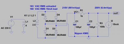
Does it worth then to make a CRC for a little more ripple rejection ?As you can see, even at 200V B+ (at this low current) the "upper" FET dissipation is marginal (small solid aluminium heatsink is enough), so there are wide range of the choice of power voltage.
View attachment 1047670
For the noise, the tube is not too noisy by it self as it is a E188CC exactly.
Each ripple rejection matters.
IMHO CRCRC filtering (few mV disturbation on output) is good for -low power- phono preamps.
IMHO CRCRC filtering (few mV disturbation on output) is good for -low power- phono preamps.
Last edited:
Thank you for the input again.
Not phono for me but few 2 mA swing from a dac chip into 50 ohms. Same quiet needs...
Not phono for me but few 2 mA swing from a dac chip into 50 ohms. Same quiet needs...
You can get something like 3mV ripple with 0.1uF//VR150.
A CCS filter is really effective at removing ripple and provides good isolation, you could get away with a single filter cap.
Rectifier - (R?)C - CCS - VR150 - plate load CCS - tube ?
Transformer secondary could be anything ~160VAC to 200VAC and load current would be ~50mADC.
A CCS filter is really effective at removing ripple and provides good isolation, you could get away with a single filter cap.
Rectifier - (R?)C - CCS - VR150 - plate load CCS - tube ?
Transformer secondary could be anything ~160VAC to 200VAC and load current would be ~50mADC.
.... I really dunno as a noob, but I like the idea of at least a simple CRC before the Mu follower, just because I do not like the idea that the smoothing cap and the reservoir cap to be the same... and I use SS rectifiers.
I have not firered up PSUDII, but grossly I will make a 47 uF/600v lythic à la Epcos a 1k/13w Dale Mexico I have then same Epcos family but 220 uF. I have also the cool HV reg from Tivicol which may have perhaps a better noise rejection but it seems same thing more or less than a Mu follower but here cap multiplier !
Well I do not want to be cunterproductive...it is just a 33 Mu low voltage tubeamp after an I/V dac stage that can output 2 V RMS... I mean the main culpritt for a B+ is the ripple not so the noise (tube having its own intrensic structural noise) ?
For the Mu follower the second stage should use what I can source at Mouser... upper position to220 DN2240 and lower position J310 if remembering what said euro21 to me in an other helper thread 🙂
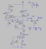
That's rock ! Not far from what I slowly try to adapt from T loesch classic circuity with the help of the Diyaudio inmates ! 🙂  I believe T Loesch applies 75V B+.
C1 R1 L1 is the deamphasis circuitry? , I can get rid of it I believe...
You put a green led in spite of Loesch 10R for cathode biass, ok
Rmu ? 470R or around 100R ? : https://www.diyaudio.com/community/...-in-an-hybrid-mu-follower.384775/post-6986364 ...
15v zener diode through holes are not sourcable at Mouser, perhaps I will use some 12V or 16V I have,
R5 : 1K in spite of 5K , ok have both 🙂
Upper classic Mostfet are out of stock
Lower j310 are on stock 🙂
i didn't know i have to populate the 10R just before the Anode, ok
C6 : I surmise a good film one
C3 : I should reduce it to around 0.47 uf with my 47K input pre to choose a cap not too much colored 🙂
For the PI power filter i will source 120 uF : much more choice due to the supply chain problem : nipon chemicon long life 500/600V, ok
220k/47k for the heater divider (or heating elevator,)...
Just have to knock at MOUSER
thanks again, that helps a lot
 I believe T Loesch applies 75V B+.
C1 R1 L1 is the deamphasis circuitry? , I can get rid of it I believe...

You put a green led in spite of Loesch 10R for cathode biass, ok

Rmu ? 470R or around 100R ? : https://www.diyaudio.com/community/...-in-an-hybrid-mu-follower.384775/post-6986364 ...

15v zener diode through holes are not sourcable at Mouser, perhaps I will use some 12V or 16V I have,
R5 : 1K in spite of 5K , ok have both 🙂
Upper classic Mostfet are out of stock

Lower j310 are on stock 🙂
i didn't know i have to populate the 10R just before the Anode, ok

C6 : I surmise a good film one
C3 : I should reduce it to around 0.47 uf with my 47K input pre to choose a cap not too much colored 🙂
For the PI power filter i will source 120 uF : much more choice due to the supply chain problem : nipon chemicon long life 500/600V, ok

220k/47k for the heater divider (or heating elevator,)...
Just have to knock at MOUSER
thanks again, that helps a lot
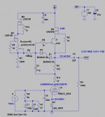
Yes, it's Thorsten's schematic adaptation.
Upper FET:
https://eu.mouser.com/ProductDetail/IXYS/IXTP08N100P?qs=jFjNEgmwGdfXc8JRp0enOQ==
Try Rmu 470R or 100R. Only minor difference will occur (at 100R the output level a little lesser).
Upper FET:
https://eu.mouser.com/ProductDetail/IXYS/IXTP08N100P?qs=jFjNEgmwGdfXc8JRp0enOQ==
Try Rmu 470R or 100R. Only minor difference will occur (at 100R the output level a little lesser).
- Home
- Amplifiers
- Tubes / Valves
- B+ : does a Mu follower need extra noise and ripple filtering from the HV supply?


