Magura said:
I think what Jacco is trying to do is to help you determine if your data is correct.........so if I were you I'd provide a link 😉
Magura 🙂
hihihihi.....maybeee he i tryig to ceack my calculation.... hihhihhihi....
tomorrow i will attach the link....
Stefanoo said:
hihihihi.....maybeee he i tryig to ceack my calculation.... hihhihhihi....
tomorrow i will attach the link....
To tell you the truth, Grey is 100% right when saying that you just need very simple calculations to make this work out......especially if you add a little common sense to the equation 😉
Take a look at
http://www.diyaudio.com/forums/showthread.php?s=&threadid=93194&highlight=
This is something along the lines of what you would want to make to achieve your goal. You could get most of the answers to your questions from that thread. (if you accept that you don't need the third decimal in the calculations)
Magura 🙂
Do you really, honestly, truly, factually need to drive a two ohm load?
Do you really?
Yes, there are speakers that have dips to uncomfortably low impedances, but there are only a few cases where the dip is over a wide range of frequencies. Ask yourself how many notes fall into that hole. One or two? Half an octave? Two octaves? How much power will one note take to reproduce?
Don't get me wrong. I overbuild amps as a matter of course. But I also water cool (most of) my amps and can afford to dump prodigious amounts of heat. Most people don't have that luxury. Then there are the transformers to worry about.
The temptation to build a "statement" piece of circuitry is sometimes irresistible, but it's not a bad idea to consider whether your intent is based on the pure sex appeal of something huge or on a realistic assessment of need.
Grey
P.S.: Common sense? Whuzzat?
To the moderators,
Most of this recent discussion belongs in the Aleph-X builders thread. Perhaps it could be moved. It would receive more attention and input. Thank you.
Graeme
Most of this recent discussion belongs in the Aleph-X builders thread. Perhaps it could be moved. It would receive more attention and input. Thank you.
Graeme
gl said:To the moderators,
Most of this recent discussion belongs in the Aleph-X builders thread. Perhaps it could be moved. It would receive more attention and input. Thank you.
Graeme
ghost in the machine................

GRollins said:Do you really, honestly, truly, factually need to drive a two ohm load? Do you really? The temptation to build a "statement" piece of circuitry is sometimes irresistible, but it's not a bad idea to consider whether your intent is based on the pure sex appeal of something huge or on a realistic assessment of need
As if there's a difference.
gl said:Most of this recent discussion belongs in the Aleph-X builders thread. Perhaps it could be moved. It would receive more attention and input.
Yes, that thread only has 209,000 views and needs a boost.
😎
aleph 1.2 to XA 160
Grey and GL, I am learning about international threads, my concern with the power supply for my project was driven by getting low audible noise from the transformer and amp. When I built the Pass Tharagard A75, I used a Dynaco A400 transformer per channel as I got them from a friend who wanted to get rid of them. They buzzed and huffed so I replaced them with an avel lindberg torroid rated at 625va and whalla no noise. This transformer was a bit oversized but the core didn't buzz. I am using the same train of thought for this project. Design the power supply per Grey's and GL's suggestions in mind but to make sure of complete silence perhaps add a few VA. It is interesting that the Pass 350.5 is absolutely silent in my system where my Aleph 1.2's -2kva Plitron torroid xformers buzz like a bumble bee in heat.
I built the 1.2's in 2000. As an amatuer I don't want to go into the xfromer testing business. I also don't have to design for an inifinite number of possibilities. And yes Grey, I am testing for DC on my AC lines this weekend. I will use my scope set to DC across the ac primary of the xformer after my line filter. Plitron says they can handle up to 250mv before the core acts up. We shall see.
Stefanoo said:have problems to catch this rule of thumb of "6".
I estimate the necessary transformer size based on the "target +/- rail voltages" and the "target current draw". I think Papa explains it in his project paper of Zen V5, referring to the primary and secondary schools.
By the way, do you know who Papa is?

Nelson Pass said:
As if there's a difference.
Aye...guilty as charged. I've done the pull-out-all-the-stops thing as often as any ten other members combined. Which is what led to my postscript.
The trick is to achieve a sort of glorious gonzo balance in the insanity--sort of like the inverse of the fabled One Hoss Shay in which all the parts failed at the same time. You have to get each and every part to precisely the same level of excess or the thing doesn't work right. There's some sort of cosmic yin/yang principle at work here. If I could only express it mathematically, I'd get an award of some sort.
(Probably Ignoble, but let's not count that particular chicken before it hatches.)
Grey
P.S.: Anyone who doubts my tendency to excess should be aware that I'm working on the PCB artwork for a 25W/8 Ohm amp that will have sufficient bias to run my ribbon drivers directly without current limiting.
So there.
GRollins said:
................If I could only express it mathematically, I'd get an award of some sort.
(Probably Ignoble, but let's not count that particular chicken before it hatches.)
Grey
.....................
I presume that even Nebula will be fine 😉
It's unlikely that I'll ever get a Nebula. I'm not good at playing politics. Besides, I don't write for other authors (some do), I write for readers.
I've got about nine hundred things on my to-do list today, but hope to get back to the PCB artwork by late this afternoon. It's a double sided board, so I have to be extra careful to make sure everything gets where it's supposed to go.
Grey
I've got about nine hundred things on my to-do list today, but hope to get back to the PCB artwork by late this afternoon. It's a double sided board, so I have to be extra careful to make sure everything gets where it's supposed to go.
Grey
GRollins said:It's unlikely that I'll ever get a Nebula. I'm not good at playing politics. Besides, I don't write for other authors (some do), I write for readers.
................
Grey
hehe......I knew that things are the same everywhere ....... 😉
Babowana said:Boyz! Back to the topic!
Trying to be puched away?
: on be half of the mods:
I'll send you to Serbia (Texas?) if you don't stop with behaving good
Zen Mod said:I'll send you to Serbia (Texas?)
Uhh . . . ? Are you an honored moderator at diyPiPi?
If so, I could easily guess its quality . . .

aleph 1.2 to AX100/160
Gl, I spent some time with my parts bin at home after working on the lawn. The new circuit board will be pt to pt. Looking at my Aleph 1.2 output stage I noticed that I have 1.5ohm source resistors vs the 1.0 ohm that you used. The thought of redoing 24 output devices is more work than I want to do so for now I will leave them in. The output impedance with 6 fets per quadrant should still be low enough. My Alephs have about 8 amps of bias to get 200watts output and my heat sinks run hot at about 50-55 degrees C. My thermal switch has never activated in 7 years so this is the max dissipation the chasis can handle. If I plan to run around 32 volt rails and 600ma per device or 7.2 amps of bias what would you estimate my output to be?
I am going to use 1kva trannies with 25vac rails or 35 volt dc rails unloaded which means most likely +/- 32 volts. The voltage drop accross the output source resisotors would be 600ma x 1.5ohms or .9v.
I believe that my source resistors are 2watt or 5 watt devices.
The aleph drops .5volts but it has 12 devices per rail.
Of course I don't have to run the bias this hard and use your bias of 540ma per device x 6 devices x 2 = 6.4amps. dave
......GL, I spoke to Meloney at Avel-lindberg xformers. She recomended their 1kva trannie with two 25vac secondaries rated at 20 amps each
Since I will use this to biamp the tweeter section of my line arrays, I should be ok with the power.
perhaps, if your tweeters are very senstive (horns, I hope). If not, you can always build another one and run them bridged.
😉
JJ
aleph 1.2 to XA100
J--true enough, I was thinking of using two 625va trannies per channel, one for the positive rail and one for the negative rail, more VA but more imortantly-quieter. More parts but if this amp lasts the 7 years like my Aleph and 15 years like my A75 it might be worth it. dave
J--true enough, I was thinking of using two 625va trannies per channel, one for the positive rail and one for the negative rail, more VA but more imortantly-quieter. More parts but if this amp lasts the 7 years like my Aleph and 15 years like my A75 it might be worth it. dave
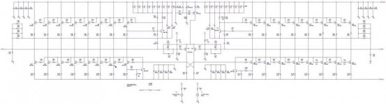
As i previous posted i'm tryng to build an high current version of the aleph xa 100.
The output stage is made with 8 mos per quadrant (total of 32 mos per channel).
The bias current of each mos is about 1.4A at +-26V rail supply voltage.
The minimum estimated drivable load is 2ohms.
The AC gain is around 17dB.
The power that this amp can deliver is
130W @8ohm 260 @4ohm 520@2ohm (peak power)
If the behaviour is ok, i'll go on and i'll build the PCB Board.
What makes me wonder is that the current on the mosfets on the top and bottom quadrant are different.
In particular the mosfets on the bottom draw more current than that on the top.
The idle power dissipation is not the same as well.
On the top mosfets i have aroud 36W, insted on the bottom mosfets 35W (not big different thought)
Is this normal?
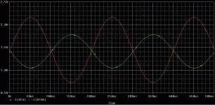
Here some significant screenshoots.
The schematic (hope you guys can see it...i had to resize it a lot!)
The output stage is made with 8 mos per quadrant (total of 32 mos per channel).
The bias current of each mos is about 1.4A at +-26V rail supply voltage.
The minimum estimated drivable load is 2ohms.
The AC gain is around 17dB.
The power that this amp can deliver is
130W @8ohm 260 @4ohm 520@2ohm (peak power)
If the behaviour is ok, i'll go on and i'll build the PCB Board.
What makes me wonder is that the current on the mosfets on the top and bottom quadrant are different.
In particular the mosfets on the bottom draw more current than that on the top.
The idle power dissipation is not the same as well.
On the top mosfets i have aroud 36W, insted on the bottom mosfets 35W (not big different thought)
Is this normal?
Here some significant screenshoots.
The schematic (hope you guys can see it...i had to resize it a lot!)
Attachments
Hi Dave,
.9 V across those resistors feels a bit high. I don't know if you'll be able to adjust the bias enough on the BJT control transistor to get the CCS to work right. My choice would have been to solder another 1.5 ohm resistor across each existing one and create .75 ohm source resistors.
With 7.2 amps of total bias and an 8 ohm load you would have just over 207 watts of output power. Your voltage rails (by my calculations which could be wrong) would limit your output at 225W at which point your bias would have to be 7.5A.
Stephano,
I can't comment because I have never simulated this circuit or used your simulator software.
Cheers,
Graeme
- Status
- Not open for further replies.
- Home
- Amplifiers
- Pass Labs
- AX100 100W Aleph-X Monoblocks