Hi, I would like to extract a coaxial digital output from my Denon x3600h, for the front and left front channels. I saw this video:
I think with your help I will be able to do it.
Unfortunately the video is in English and I can't use the translator, everything isn't very clear to me.
I bought the service manual for my Denon.
Can anyone help me understand which are the 5 points where I have to solder the 5 wires.
From the video I think I should look for:
SCK
BCK
LRCK
DATA 1 L/R
GND
+5V
...but in the end won't they have the same names? Because in the video he is modifying a Yamaha.
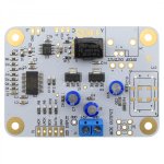
The board he recommends purchasing is this:
https://www.audiophonics.fr/en/inte...rs-spdif-bnc-wm8805-24bit-192khz-p-12561.html
Board have this connection:
MCK
LRCK
BCK
DATA
GND
My output dac is AK4458.
I think I have to connect to the pins (pads) of the AK4458, but I'm not sure which ones. Then they thought about getting the +5v.
Thanks for any help.
I think with your help I will be able to do it.
Unfortunately the video is in English and I can't use the translator, everything isn't very clear to me.
I bought the service manual for my Denon.
Can anyone help me understand which are the 5 points where I have to solder the 5 wires.
From the video I think I should look for:
SCK
BCK
LRCK
DATA 1 L/R
GND
+5V
...but in the end won't they have the same names? Because in the video he is modifying a Yamaha.
The board he recommends purchasing is this:
https://www.audiophonics.fr/en/inte...rs-spdif-bnc-wm8805-24bit-192khz-p-12561.html
Board have this connection:
MCK
LRCK
BCK
DATA
GND
My output dac is AK4458.
I think I have to connect to the pins (pads) of the AK4458, but I'm not sure which ones. Then they thought about getting the +5v.
Thanks for any help.
Attachments
They will not be the same.
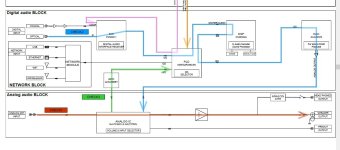
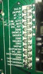
For the Denon it is -
DACMCK - Master or System clock.
DACBCK - Bit clock.
DACLRCK - Left/Right clock.
DACPCMF - Front channels left and right.
DACPCMCSW1 - Centre and subwoofer 1 channels.
DACPCMSW2RSV - Subwoofer 2 channel and reserved(no analogue output).
DACPCMS - Surround channels left and right.
DACMCK - MCK
DACBCK - BCK
DACLRCK - LRCK
DACPCMF - DATA
The service manual will provide the information on where to tap 5V and GND.
Thanks for the help, very much appreciated.
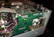
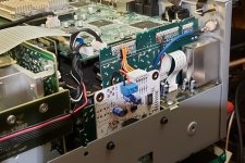
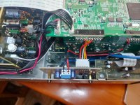
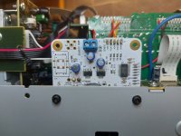
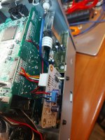
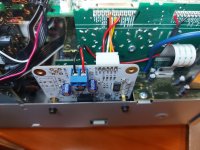
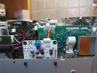
I located the AKM that runs F/L Front. It is on a vertically positioned board that connects to the digital main board.
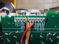
There is a connector that connects the two boards. I think that connector is the right place to get the signals.
The connector is located 3cm from the AKM and 5cm from the chip it connects to.
Do you think it might be a good place to get the signals? Let's say it's quite comfortable.
I think there are also GNDs on the connector where I would get the signals. On the other connector I see that there are +5v and GND.
I don't know which ones I have to take to power the board (+5v/GND) and which ones I have to take as digital GND (the fifth wire of the group of 5 wires).
Can you understand it? Thank you again
I located the AKM that runs F/L Front. It is on a vertically positioned board that connects to the digital main board.
There is a connector that connects the two boards. I think that connector is the right place to get the signals.
The connector is located 3cm from the AKM and 5cm from the chip it connects to.
Do you think it might be a good place to get the signals? Let's say it's quite comfortable.
I think there are also GNDs on the connector where I would get the signals. On the other connector I see that there are +5v and GND.
I don't know which ones I have to take to power the board (+5v/GND) and which ones I have to take as digital GND (the fifth wire of the group of 5 wires).
Can you understand it? Thank you again
Attachments
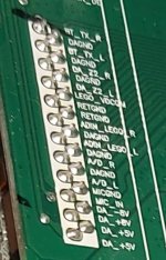
With the DAC signals I would use one of the DGND ground pins. For power to the board I'd use DA_ +5V and DAGND

thanks friend. I had thought the exact same things but being a beginner I always ask those who know (certainly) more than me! Good night! <3
@rfbrw
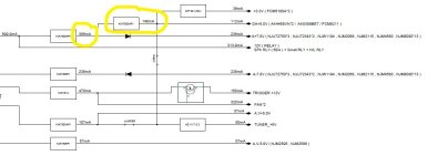
Hi! good evening 🙂 The additional card consumes 35mA on one branch (7808) with already 386mA.
I connected it to a 7805 which takes power from a 7808.
Will it be fine or is the absorption too high?
I don't think so but I'm asking.
Thank you
Hi! good evening 🙂 The additional card consumes 35mA on one branch (7808) with already 386mA.
I connected it to a 7805 which takes power from a 7808.
Will it be fine or is the absorption too high?
I don't think so but I'm asking.
Thank you
Attachments
-
 20231127_043302.jpg491.1 KB · Views: 108
 -
 20231127_043158.jpg533.4 KB · Views: 97
 -
 20231127_043146.jpg373.9 KB · Views: 99
 -
 20231127_043117.jpg451.8 KB · Views: 96
 -
 20231127_043101.jpg387.7 KB · Views: 92
 -
 20231127_043052.jpg407.9 KB · Views: 102
 -
 20231127_043042.jpg452.1 KB · Views: 110
 -
 20231127_043028.jpg417.6 KB · Views: 106
 -
 20231127_043022.jpg400.2 KB · Views: 100
 -
 ALIMENTAZIONI DENON 78XX.jpg54.3 KB · Views: 110
1. You can do the same for any of the other channels.
2. According to the datasheet the 7808 regulator has a rated output current of over 1000mA.
2. According to the datasheet the 7808 regulator has a rated output current of over 1000mA.
thanks for reply. i have some questions.
do you think I won't have clock or jetter problems both with this mod and with a possible other release for subs?
To the output I created (front) I connect a 10x10 minidsp. Will the clock and digital signal level issue be ok?
What comes out of the denon on the digital output I created?
What characteristics does the signal have?
Thank you
@rfbrw
Hi, sorry to bother you again. I have a problem.
I realized that when Audyssey sends the sweeps from the various channels, as far as the digital output is concerned, I find that when it sends the sweep on the left channel I don't hear anything, when it sends it from the right channel I hear it on both channels, i.e. front R and L.
How can this be? The digital signal is unique and contains both channels. Is absurd.
I connected a frequency generator to an analog input on the Denon... and it's actually the same.
The Denon outputs "dual mono" from the digital output. Do you have any idea?
I do not! 🙁
What happens when you disconnect the SPDIF board ?The Denon outputs "dual mono" from the digital output. Do you have any idea?
I do not! 🙁
@rfbrw
HI, I did a couple of tests.
First of all I wanted to correct this:
From the implemented digital output (white board, i2s>digit coax), I hear the left channel of the Denon (music and audyssey sweep) on both speakers (passing through an external DAC). No good! 🙁
Same thing even with audyssey off, so no environmental correction. I had said that the channel I heard was the right. Mistake! Little difference, the problem is the same!
If I connect the amplifier and speakers to the front preout output... everything is fine (both music and audyssey sweep)... even with the white board (i2s>digit coax) installed and connected (to the input of the AKM Denon) .
I can't have two external DACs with two digital outputs because I need a single digital output (left and right)... to enter a 10x10 miniDSP that I use as an electronic crossover to drive 3-way speakers (3 amplifiers).
What type of logic analyzer could I buy? There is an analog oscilloscope and a digital USB (PC) oscilloscope... but they do not analyze digital signals.
One question: For direct mode just go to the menu and turn off audyssey, correct?
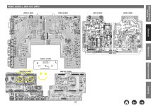
However, I carried out some trivial measurements with a USB oscilloscope / PC. I measured all signals on three different points.
On the connector of the original denon board (where I get the signals from), on the white connector of the white board..and on the pins of the WM8805.
The 3 point signals are always the same, except for the MCK.
MCK on the connector of the original Denon board.. I measure 78Khz/890mv, on the white connector of the white board I measure approximately the same voltage but 87khz, and, on the pin of the WM8805 (pin 20) I measure 34khz/800mv. Maybe this thing isn't important.
Furthermore, on pin 19 of the WM8805 I measure 48Khz (I think this is normal).
I wanted to add something. Inside the Denon there are two 8-channel AKM DACs...but the Denon doesn't have 16 output channels!
Maybe they put some channels in parallel?
But I don't know, I get the signal at the entrance to the AKM. I'm attaching an pdf schematic file anyway, I don't know if it's useful.
many thanks for any help. 🙁 .... 🙂
HI, I did a couple of tests.
First of all I wanted to correct this:
From the implemented digital output (white board, i2s>digit coax), I hear the left channel of the Denon (music and audyssey sweep) on both speakers (passing through an external DAC). No good! 🙁
Same thing even with audyssey off, so no environmental correction. I had said that the channel I heard was the right. Mistake! Little difference, the problem is the same!
If I connect the amplifier and speakers to the front preout output... everything is fine (both music and audyssey sweep)... even with the white board (i2s>digit coax) installed and connected (to the input of the AKM Denon) .
I can't have two external DACs with two digital outputs because I need a single digital output (left and right)... to enter a 10x10 miniDSP that I use as an electronic crossover to drive 3-way speakers (3 amplifiers).
What type of logic analyzer could I buy? There is an analog oscilloscope and a digital USB (PC) oscilloscope... but they do not analyze digital signals.
One question: For direct mode just go to the menu and turn off audyssey, correct?
However, I carried out some trivial measurements with a USB oscilloscope / PC. I measured all signals on three different points.
On the connector of the original denon board (where I get the signals from), on the white connector of the white board..and on the pins of the WM8805.
The 3 point signals are always the same, except for the MCK.
MCK on the connector of the original Denon board.. I measure 78Khz/890mv, on the white connector of the white board I measure approximately the same voltage but 87khz, and, on the pin of the WM8805 (pin 20) I measure 34khz/800mv. Maybe this thing isn't important.
Furthermore, on pin 19 of the WM8805 I measure 48Khz (I think this is normal).
I wanted to add something. Inside the Denon there are two 8-channel AKM DACs...but the Denon doesn't have 16 output channels!
Maybe they put some channels in parallel?
But I don't know, I get the signal at the entrance to the AKM. I'm attaching an pdf schematic file anyway, I don't know if it's useful.
many thanks for any help. 🙁 .... 🙂
Attachments
I'm a little ashamed. The problem was in a minidsp setting.
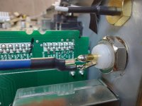
I was convinced that I had also tested an audiolab m-dac... but then I remembered that when I was about to test with audiolab... the coaxial digital out connector broke... and it distracted me... I ended the test due to a broken connector...and also because I was very angry.
I apologize if I stressed you out. I learned some things though!
- Home
- Source & Line
- Digital Line Level
- AVR Denon X3600H... MOD for Digital Output L and R Front Channel