
Given the older thought process, if I were to do these calculations by hand I'd assume a single point as a source. Using a finite cone area would take several times as long to do, and would only create less relevant data. Perhaps I'd take on a single finite case in low resolution to see how it differs from the default, before moving on.AFAIK Olson used enclosures with (diagonal?) sizes at least five times the cone diameter.
The spreadsheets we have can do finite sources, but tend to have limitations. They might use a fixed level at several points on the surface of a disc to the edge. They might not do driver directivity, or if they do it might be simplified. They don't do breakup, and don't account for cone shape.
TY will do, something came up so I will get to this in time. The instructions are exactly as I thought and needed confirmation I was on the right trackjimbones,
you could try to measure the baffle step as follows, since your bass driver is quite smooth upto 1k
put boxes in desired position and measure bass driver only without any filters
put mic at listening position, try ungated with 1/3 smoothing, measure L/R separately
Interesting, markbakk. Many questions remain.
No doubt he would have subtracted the resonant behaviour of the driver by hand. The mounting conditions necessarily controlled by sticking only to lower frequencies.
https://www.diyaudio.com/community/threads/speaker-idea-am-i-mad-or-not.314983/post-5322965
No doubt he would have subtracted the resonant behaviour of the driver by hand. The mounting conditions necessarily controlled by sticking only to lower frequencies.
https://www.diyaudio.com/community/threads/speaker-idea-am-i-mad-or-not.314983/post-5322965
Check why system response is below the response of midrange in the 1k to 3k area. Check phase tracking graphs.All, my woofer is the SB34NRXL75-8 and is 3rd order. The mid is AC130F1. 2nd order. The slopes seem to match pretty decently between woof and mid. Thoughts?
View attachment 1285324
Freeware The Edge is easy sim for baffle effects https://www.tolvan.com/index.php?page=/edge/edge.php
- Edge cannot implement driver's response, it uses a planar membrane and flat response. Baffle edges are sharp, depth unknown.
- off-axis response depends on driver diameter, you can study that by offsetting the mic!
But remember that cone and dome behave differently when wavelength is shorter than diameter of membrane
"Baffle step" is not like a step on ladders, but a slope! In 3-way typically only the woofer must have compensation for the slope and gain. With passive speaker, mid and tweeter must be attenuated!
Only anechoic or outdoor measurements are better than Edge sim!
Room response is however most important for low bass, it is affected by room dimensions and speaker placement. When using dsp, don't sress too much with low end response simulations!
Last edited:
What happens if I don't?With passive speaker, mid and tweeter must be attenuated!
Shall I respect the thermic limit of small VCs?. Should I rely on the crest factor?
pico, say woofer's nominal sensitivity is 86dB, mid 91 and tweeter 90. Full baffle step compensation is 6dB, typically designers use 3-4dB. This means using serial resistors for mid and tweeter to suppress them down 6-10dB!.
If you don't attenuate mid and tweeter, you must somehow equalize the input signal (use bass level adjust like we did in '80s) That will stress the woofer as well as eq done with xo circuit to get same overall nominal spl for the system/speaker.
If you don't attenuate mid and tweeter, you must somehow equalize the input signal (use bass level adjust like we did in '80s) That will stress the woofer as well as eq done with xo circuit to get same overall nominal spl for the system/speaker.
Your numbers are...strange for me. Also the age, I mean...In the eighties I used alot of subsonic & low cut, and also the high cut but that didn't prevent to overcome the clipping distortion that burned and burned tweeters and...
I don’t know, but finding a 7/8” cone driver with fs below 100Hz is hard even these days. So yes, probably.No doubt he would have subtracted the resonant behaviour of the driver by hand.
i ended up playing with some resistors (2 or 3 ohms) on the mid/tweet and it is helping. But I need to make measurements to confirm what I hear and to dial in correct values.
The baffle correction is a step, while the crossover is a continuously dropping response.Hi All,
My baffle width is 16 inch the step frequency comes out to 285hz. I crossed over my woofer at 285hz. I pad down the mid and tweet. Is that an acceptable alternative to adding the baffle step compensation circuit?
So that's two different things, one cannot replace the other.
Jan
OK I have a question. If I use the Baffle Step calculator (6db) requires a 3.4mh coil 6 ohm resistor. I can do 3 db and it would be a 1.4mh and 2.5ohm resistor. Does this take the place of the existing crossover in the woofer section? in addition to?
The question in post#1 was "I pad down the mid and tweet. Is that an acceptable alternative to adding the baffle step compensation circuit?"
The simple answer is NO. Padding M and T is secondary, because BS compensation of the W will reduce it's output. If one does nothing to eq the woofer's farfield response and pads down M and T, there will be a bump in upper bass just below WM xo (assuming all drivers have same nominal sensitivity)
https://www.diyaudio.com/community/threads/baffle-step-compensation-how-important-is-it.252552/
https://trueaudio.com/st_diff1.htm
https://www.audioholics.com/loudspeaker-design/crossovers/#toc-h2-1
https://sound-au.com/bafflestep.htm
Last edited:
If the woofer to mid crossover is at somewhere between 0.707 to 1 times the BS(-3) then padding down the midTop works perfectly.
Exactly what i do with my big WAWs. One passive, one active.
dave
Exactly what i do with my big WAWs. One passive, one active.
dave
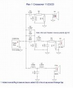
here is the crossover as modeled in XSIM. I did not take into account baffle step initially so trying to make required adjustments now. Some answers say to add the compensation before the existing XO others say to make changes to the existing XO incorporating the baffle step compensation so I am a bit confused.
Attachments
- Home
- Loudspeakers
- Multi-Way
- Avoidance of baffle step compensation