I had the idea of placing the Dave Slagle AVC (intact audio) after my LL2745 driven by my 26.
I have been reading that people experience much better results driving TCV and AVC with a low source impedance. XLR out to 30ft cables to amps.
Any limitations to this arrangement? All of my simulations result in a good response and I can drive a +6 db if phono doesn't have enough gain.(it does)
I have been reading that people experience much better results driving TCV and AVC with a low source impedance. XLR out to 30ft cables to amps.
Any limitations to this arrangement? All of my simulations result in a good response and I can drive a +6 db if phono doesn't have enough gain.(it does)
Attachments
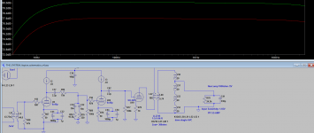
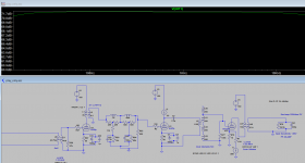
my simulations result in a good response
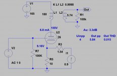
In the second stage missing ground!
If you have #26 at about maximum (safe) anode current (6mA), the bias only -60mV (10R*Ia)!
It's not working condition.
Last edited:
I had the idea of placing the Dave Slagle AVC (intact audio) after my LL2745 driven by my 26.
I have been reading that people experience much better results driving TCV and AVC with a low source impedance. XLR out to 30ft cables to amps.
Any limitations to this arrangement? All of my simulations result in a good response and I can drive a +6 db if phono doesn't have enough gain.(it does)
Output of the preamp is line level, so it should work well.
In the second stage missing ground!
If you have #26 at about maximum (safe) anode current (6mA), the bias only -60mV (10R*Ia)!
It's not working condition.
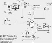
HI euro21. I have been happily using my 26 pre for a year now. The bias is -9V. Its the Gen3 bartola ( 26 DHT Pre-amplifier (Gen3) – Bartola Valves) Schematic Attached.
It uses Rod Coleman Regulators.
I did see that missing ground on stage2 and no input 100K R on the grid. Fixed it now. THANKS
Attachments
Last edited:
I was looking at the schematic and thinking.
Why not place a LCR RIAA after the LL2745 with a Zout=300 to drive a 600ohm LCR.
Follow that with the SILK TVC (Has to change from AVC to TVC to drive balanced to AMP) since the AVC cannot do balanced since LCR is SE and not BAL operation after the OPT of the 26.
I have attached a possible schematic. the gain is 52dB. a bit low but can push another +6db with the silk TVC. I will probably add the other tube with wider input range since the 6c45p cannot take the major grid swing if I chain them. back because I am not a fan of more then 1:1 interstage Ts.
Attachments
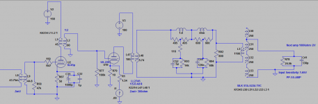
Are you sure, that it's working well?
Filament current 900mA, not 90.
If you want 2V RMS output, the RIAA gain drop about 20dB, so on second transformer secondary about 20V, on the primary 112V RMS, 158V peek, 316Vpp. Impossible.
I'm not sure, that your simulations corrects.
BTW the LCR RIAA is the most sensitive circuit. Requiring proper driving (NOT about xxx Ohm!), hate non resistive terminating (except when extra large grid coke calculated in RIAA compensation). I would not use anything else, that resistive load and active element (tube).
- Status
- Not open for further replies.
- Home
- Amplifiers
- Tubes / Valves
- AVC(TVC) after OutputTrans of 26 pre