hi friends, i need an help about my av400..
first sorry for my english, but i'ive studied it only at school, and not very well.
i saw this schema on
http://www.diyaudio.com/forums/showthread.php?postid=1106732#post1106732
and i decided to do the same amplifier, with an av400 pcb layout makes by bigpanda, with some modifications respect the original Holton's av400, but my amplifier don't work.
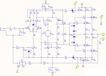
in refer to the schema shows below, my problems are these:
the transistors q6 q7 q8 q9 e q5 are quiet hot, but the real problem is that i haven't no voltage across the source's resistors.
the voltages across R2 R3 R7 R25 R29 are slightly lower of the voltages writes on the pre-flight test in the holton's document, i think that's is normal because my supply voltage is +-56v instead +-70v.
i have done all pre-flight test with a 10ohm resistor across d4-d8 (in the schema below) and after i've removed it; but at the final test i saw that i have no voltage across the sourse's resistors.
please could you help me??
thank's a lot for your time..
first sorry for my english, but i'ive studied it only at school, and not very well.
i saw this schema on
http://www.diyaudio.com/forums/showthread.php?postid=1106732#post1106732
and i decided to do the same amplifier, with an av400 pcb layout makes by bigpanda, with some modifications respect the original Holton's av400, but my amplifier don't work.
in refer to the schema shows below, my problems are these:
the transistors q6 q7 q8 q9 e q5 are quiet hot, but the real problem is that i haven't no voltage across the source's resistors.
the voltages across R2 R3 R7 R25 R29 are slightly lower of the voltages writes on the pre-flight test in the holton's document, i think that's is normal because my supply voltage is +-56v instead +-70v.
i have done all pre-flight test with a 10ohm resistor across d4-d8 (in the schema below) and after i've removed it; but at the final test i saw that i have no voltage across the sourse's resistors.
please could you help me??
thank's a lot for your time..
Attachments
You should check what you have done to the last parts if the pre-flight test is OK. I had it re-surface about 2 month ago and it gave me no problem. I was not expecting it's resurfacing would be smooth but when I set up the power supply and plug it in, everything goes on fine.
BTW, it must been over 3 years (or more?) already since you got my pcb layout, right?
BTW, it must been over 3 years (or more?) already since you got my pcb layout, right?
you should slowly turn P1 towards R21
until you have like 20-30 mV (0.02 - 0.03 Volt)
across those 0R22 source resistors in Output
this will bias each output transistor like 100-150 mA
which is what normally is good for such HEXFETs
until you have like 20-30 mV (0.02 - 0.03 Volt)
across those 0R22 source resistors in Output
this will bias each output transistor like 100-150 mA
which is what normally is good for such HEXFETs
http://www.diyaudio.com/forums/showthread.php?postid=1611519#post1611519
http://www.diyaudio.com/forums/showthread.php?postid=1613186#post1613186
why start a new thread for the same question asked in two other threads?
http://www.diyaudio.com/forums/showthread.php?postid=1613186#post1613186
why start a new thread for the same question asked in two other threads?
TO AndrewT
sorry, but i when i start my post don't knew where, and i wrote on 2 existent post, and after i decided to do a new discussion because the posts was inactive from a long time..
TO lineup
thanks for your suggestion.
TO bigpanda
in first.. thanks a lot for your pcb!! but i haven't anderstand very well what you are saying.
the pcb that i'va used is attached below. i had cheked out every connection, every path on the pcb with the schema, and it's all correct, i think that your pcb is perfect!!
but i discovered that my mosfet are fake!!!! i bought them at the electronic fair 2 month ago, and i haven't test them first.
i mount on the pcb 5A fuses. i do a preflight test, and it was all ok. after i soldered the mosfets and i turned the p1, and there wasen't voltage across the source's resistors, but at the 70% of the total circular of the trimmer, the mosfets and the fuses burn!!i was mesuring the voltage across the source resistor, but there was no voltage,and suddenly i saw voltage accross thi resistor and all burn!!
now all components are ok, and i attend for a new mosfet!!
irfp240 and 9240 supports over 5A, but, my mosfets burn all, with 5A!!
thaks a lot guys for your time, i write you as soon as i have some news about my amp..
bye
Attachments
- Status
- Not open for further replies.