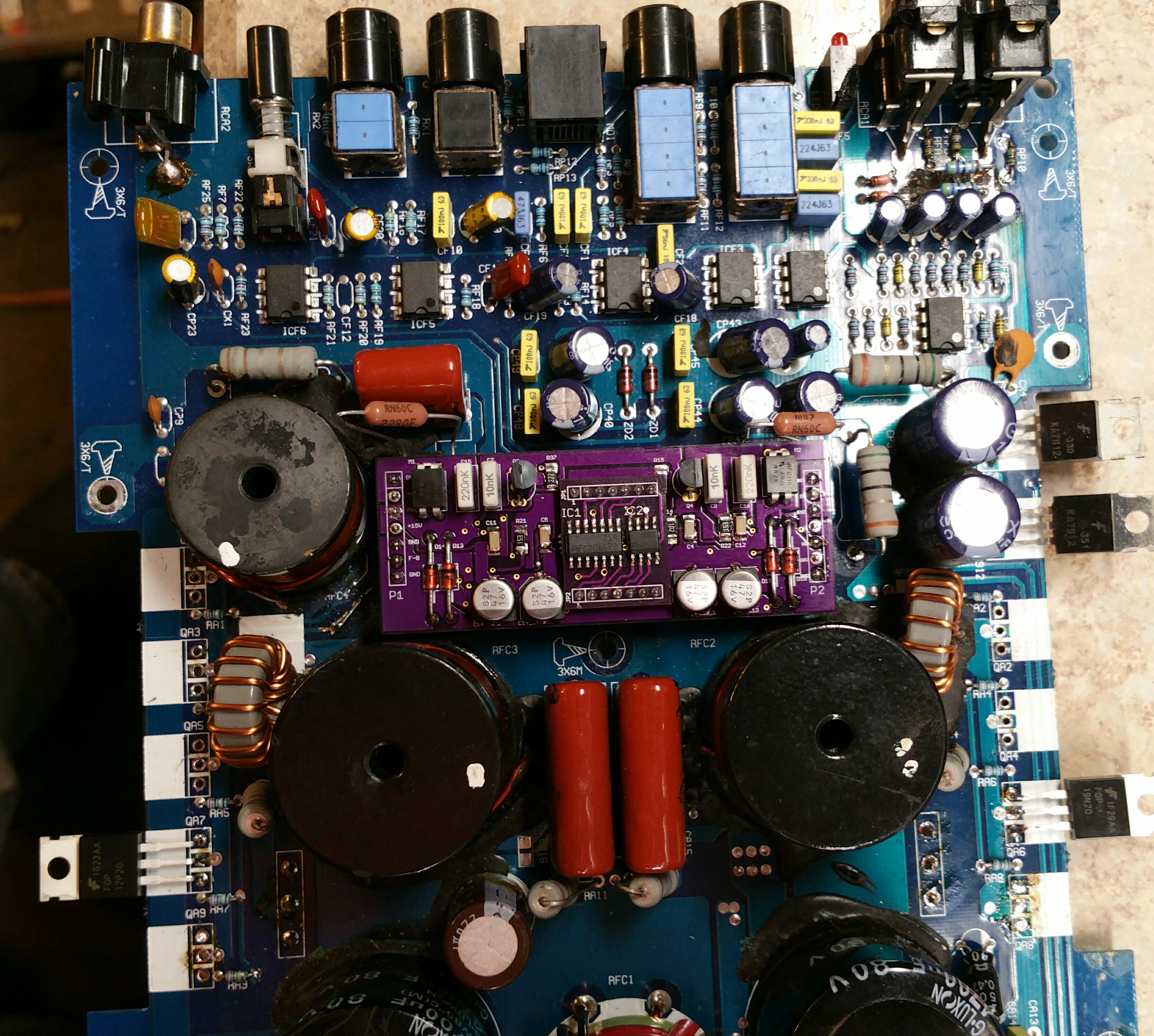
Hey folks, I decided to take inventory of this amp and see if I can get a parts order together. This thing is a complete basket case, probably not really work repairing, but I used to have a MX3000.1 and the thing was a beast, so I'd like to try to repair this is possible. Cosmetically it is in decent condition, so if I can pull it off it will be a nice amp to have around.
Below you can see what I need some help with. This thing has been butchered. First, I need to know if anyone has schematics or can point me toward a similar design for the input section. It is totally torched and then hacked and then cobbled. Next I need to know if the FQP12P20 are the right mosfets for the outputs. Any idea what the gate resistors should be, I see three different varieties... Last is the DLM driver board, but I think I already have that info, but if anyone spots something I overlooked, please speak up!
Thanks so much!
Jason
http://www.bcae1.com/temp/IMG_6554.JPG
http://www.bcae1.com/temp/IMG_6556.JPG
http://www.bcae1.com/temp/IMG_6561.JPG
http://www.bcae1.com/temp/IMG_6562.JPG
These are from a 3000 but they should be the same. I don't have a diagram.
http://www.bcae1.com/temp/IMG_6556.JPG
http://www.bcae1.com/temp/IMG_6561.JPG
http://www.bcae1.com/temp/IMG_6562.JPG
These are from a 3000 but they should be the same. I don't have a diagram.
Thanks Perry! That is perfect. Out of curiosity what are the pink(ish) components silkscreened CFA3?
Ceramic capacitors, most likely.
CFA is probably Capacitor Filter Audio Looking at it again, the A may be a input and a B would be the other channel. In other words, I'm not sure.
The capacitors with P in the designation are power supply caps.
CFA is probably Capacitor Filter Audio Looking at it again, the A may be a input and a B would be the other channel. In other words, I'm not sure.
The capacitors with P in the designation are power supply caps.
Last edited:
Hi guys, I spent a little time on this amp today, trying to see what all it needs and it has me a little bit stumped at the moment.
Here is where I am at: I replaced the missing LM219 from the driver board and the TL072 just for good measure. I removed all the crap that was bodged in and all the parts that were in the way of doing a proper repair of the burned section near the input jacks. I then hooked it up to the power supply with a 2 ohm limiter, amp would not power up, the current limiter was dropping the supply voltage to about 5V from ~13.5.
I then pulled all the output transistors. Most tested okay, but there were a few that were bad according to my super cricket, so problem solved? Nope, put it back on the supply and now it is not pulling excessive current, but the power supply still is not coming up. I check the TL494 and on the first error amp had non inverting input at ~3V and the inverting input at 9V. Second error amp was 0V on the non inverting and 4.9V on the inverting. Vref was at 4.9 and no output on pin 9 and 10.
So, I thought that maybe there was a shorted fet in the power supply. Testing in circuit had some weird results on only one of the two banks. I pulled them all with the intent of checking each part individually and then just putting two fets for testing. I did find several weird fets in the bunch. By weird I meant that the a few would show gain for less than a second, and then register as bad unless I disconnect and then reconnect. I also found that these "weird" fets would test mostly ok with their source and drain reversed. I have never seen any fets test like this on my cricket, and I have had it for years. Anyhow, I fire it up with no outputs and no power supply fets and check out the power supply drive, it has a good square wave and the TL494 error amps are at 2.5 & 2.5 on error amp 1 and the second is still at 0 and ~4.9. The output pules is at ~30khz and looks really good. So, I put one pair of good fets in it, and we are right back to square one. The TL494 is not pulsing and error amp one is back to 3&9V.
So, I pull the big rectifiers. This amp has one set by the power supply and one set sandwiched between the board and the heat sink back by the output fets. I am not sure exactly what the sandwiched pair are for yet, it was getting down toward the end of my shop time and I didn't have a chance to trace it out. With all 4 rectifiers out of the board, I power it up and now the TL494 is working fine again. I have about 60Vac on both secondaries.
Here is why I am a bit mystified by this. The issue has to be somewhere downstream of the rectifiers. I believe it is the feedback to error amp 1 that is shutting down the supply. What doesn't make sense to me is that that voltage being fed back to the TL494 seems to derived from the 12V supply. Unless I am missing something, it has to be, because the switching supply will not run. So why when I remove the power supply fets do I get a good drive signal and the error amp goes to 2.5&2.5?
I'm sorry for the really long winded post. I have been turning this over in my mind all afternoon and I am just not seeing it. I will have time for more troubleshooting tomorrow, so I guess worst case scenario I start going through it part by part until I find what is out of spec. Hopefully one of you might be able to offer some insight on where to point my attention first.
Thanks,
Jason
Well, I got the power supply working today. I am not sure what was causing my issues, but I cleaned all the pads for the outputs and replaced a small electrolytic capacitor that had vented and put one set of rectifiers back in and if all worked, so I put in the other set and it was still ok so either I had a bridge somewhere or it was something to do with the bad cap.
So I went on to repair the input section that was burned, then I put one output in each back and tried to power it up. Power light would just flicker while trying to power through 2 ohm limiter and both outputs getting hot. I then tried to power through 1 ohm limiter with similar results. I pulled the outputs back out and checked the gate drive. I'm not certain, but based on my mx5000 the gate drive for both high and low side is supposed to be a square wave. The screen shots below are what I'm getting on the gates.

N channel gate drive
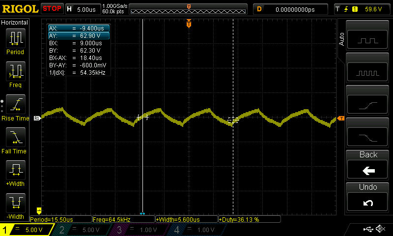
P channel gate drive
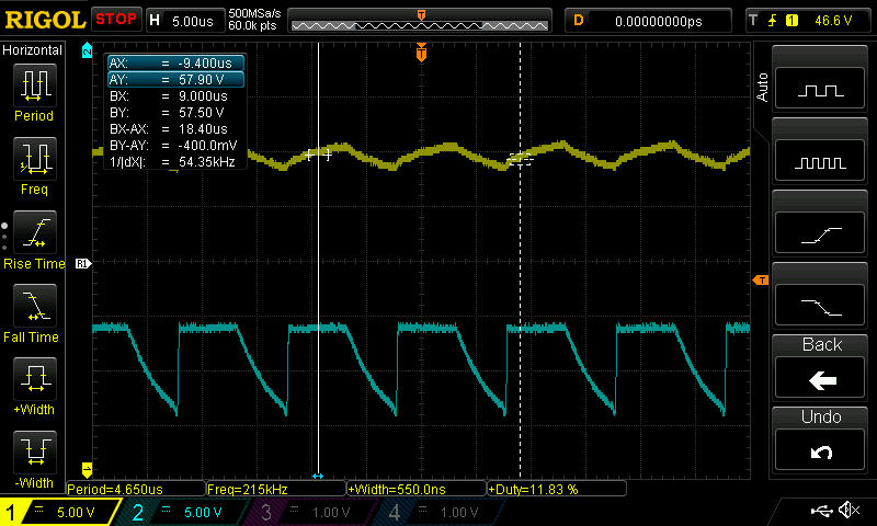
Does anyone have any advice on where to start on the driver board? I'm guessing from the looks of the N channel drive that it they use a push/pull pre driver that one side of it might be leaky. I don't know about the strange triangle wave, I'm hoping someone will have some insight.
Perry, a question specific to you, are the DLogixs driver boards covered somewhere in the tutorial? I haven found them in the class d specific pages.
Thanks guys!
Jason
So I went on to repair the input section that was burned, then I put one output in each back and tried to power it up. Power light would just flicker while trying to power through 2 ohm limiter and both outputs getting hot. I then tried to power through 1 ohm limiter with similar results. I pulled the outputs back out and checked the gate drive. I'm not certain, but based on my mx5000 the gate drive for both high and low side is supposed to be a square wave. The screen shots below are what I'm getting on the gates.
N channel gate drive
P channel gate drive
Does anyone have any advice on where to start on the driver board? I'm guessing from the looks of the N channel drive that it they use a push/pull pre driver that one side of it might be leaky. I don't know about the strange triangle wave, I'm hoping someone will have some insight.
Perry, a question specific to you, are the DLogixs driver boards covered somewhere in the tutorial? I haven found them in the class d specific pages.
Thanks guys!
Jason
The only information would be in the Performance Technique folder. I think the only thing useful will be the waveforms on the header pins on the SWF file. Remember that you can right-click to zoom.
Without a reference (rail, voltage, ground...), the waveforms are mostly meaningless.
Without a reference (rail, voltage, ground...), the waveforms are mostly meaningless.
Thanks Perry, I will check out that folder. The waveforms at the driver board were what I was hoping to find.
The waveforms above were taken with secondary ground as reference. Rail voltage on this amp is +/- 73Vdc.
I have the driver board pulled from the amp again. I am going to go through all the transistors and what appears to be several SOT-23 cased zener and switching diodes. I'm tempted to pull a driver from one of my MX5000's working channels, but I really don't want to risk pulling a via unless I have to... If I don't find anything glaringly obvious on this driver, I will have to try one of the others to make sure I am on the right path.
Thank you for your help. I appreciate it!
Jason
Well, I got my dlm clone board finished today and I put it in the mx1500. I only popped in one pair of outputs and it immediately shorted the p-channel fet. So I figured my driver board was the problem, pulled the outputs and did what I should have done at the beginning and checked the waveforms against the tutorial. Everything checked out pretty much perfect, so I kept looking. Well, there was a open trace on P-channel gate drive, under the black fixative. I fixed that and put a fresh pair of outputs in and powered it up again. This time no blown parts, but as soon as the relay pulled in it had a super high pitch squeal. I'm thinking that something is wrong with the output filter. I'm going to put my dlm into my working mx5000 to ensure that's not the problem, but I really don't think it's the issue.
Pics for proof is in there. Had to bodge in a pair of 22r resistors, my ones I ordered still haven't shown up yet...
Pics for proof is in there. Had to bodge in a pair of 22r resistors, my ones I ordered still haven't shown up yet...
Well, I am back to work for a few nights, but I am trying to work out what might be causing this amp's output issues.
A few notes I didn't include above because I got sidetracked. First off, the high frequency whine I get out of this after I put a pair of outputs in is audible from one of the output inductors before the muting relay pulls in. When the relay engages it can be head from the speaker as well.
I briefly tried twisting and pulling on the loose inductors, no change, but I did not have a lot of time to try.
This is the amp that had a lot of the input section burned away. I did check and I do have clean audio at the input on the DLM board, so I am thinking it is not a preamp issue.
The reason I am thinking it is a output filter issue is mainly because the frequency of the whine is much higher than anything the amp should be able to pass. We are talking at the upper ranges of average hearing. Probably ~15kHz. I know I didn't like it, and my dog liked it less!
Do any of you have a schematic of a similar style output filter. I did not have time to take a bunch of detailed pictures, but it appears it has 5 different output inductors, not to mention some big ceramic caps and a single electrolytic.
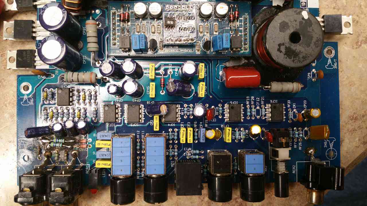
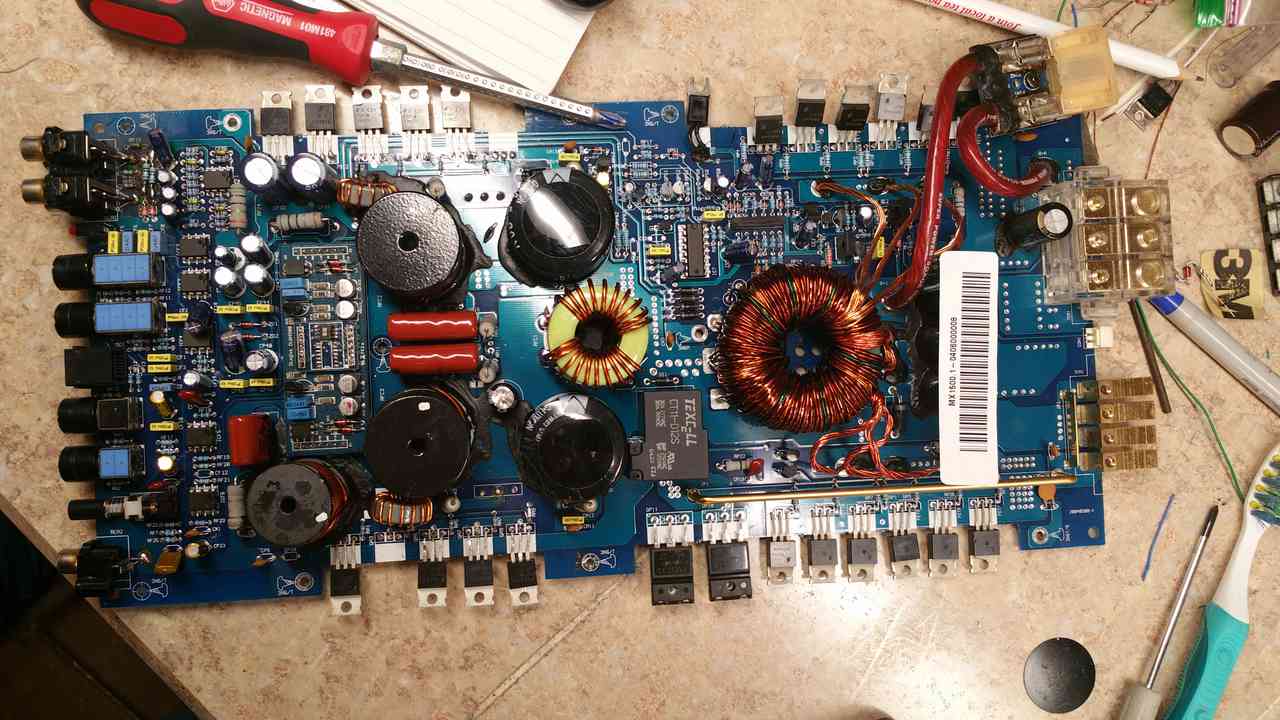
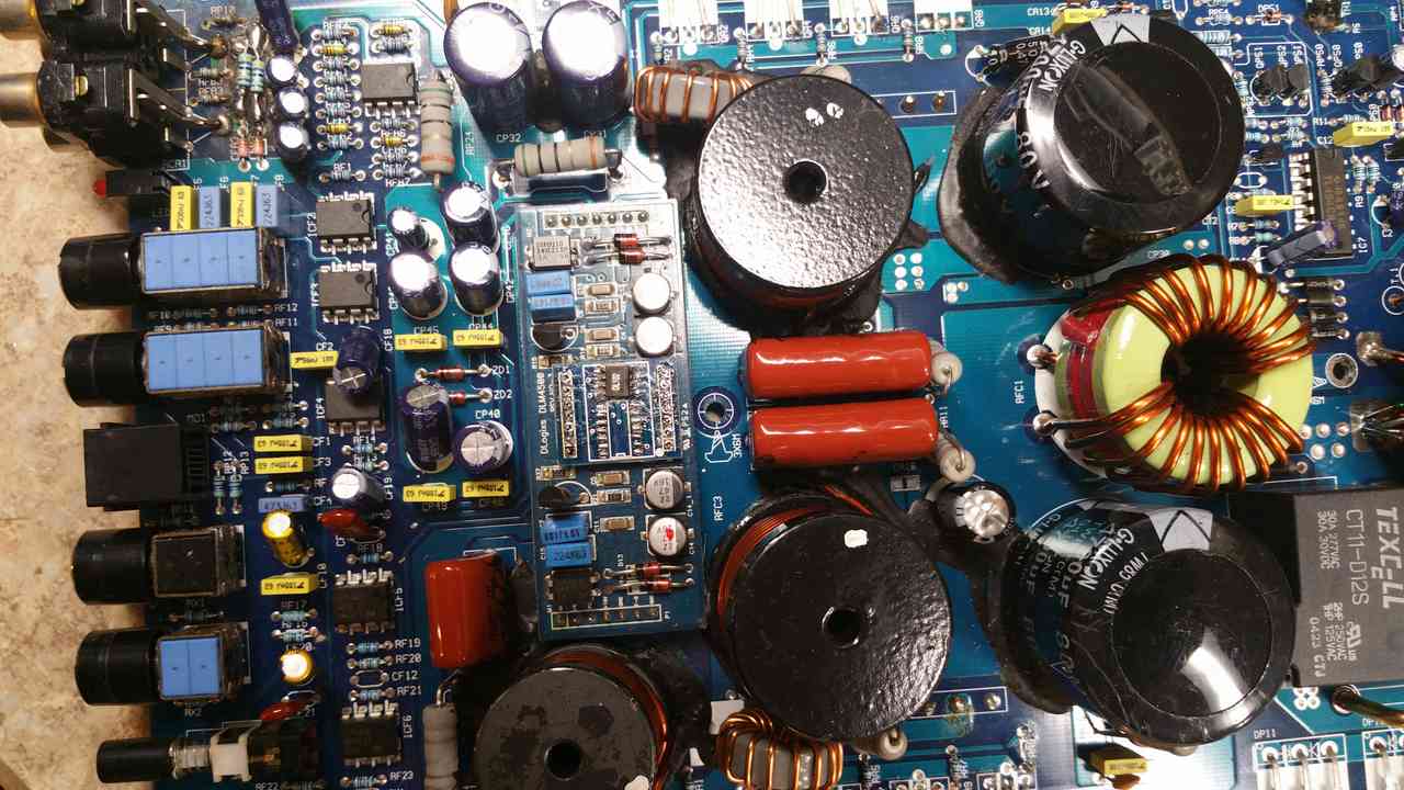
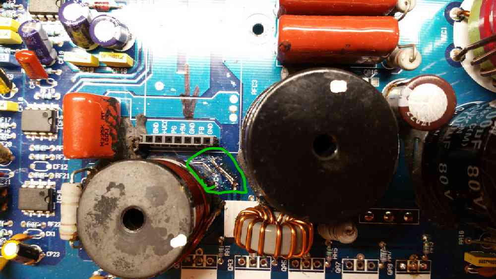
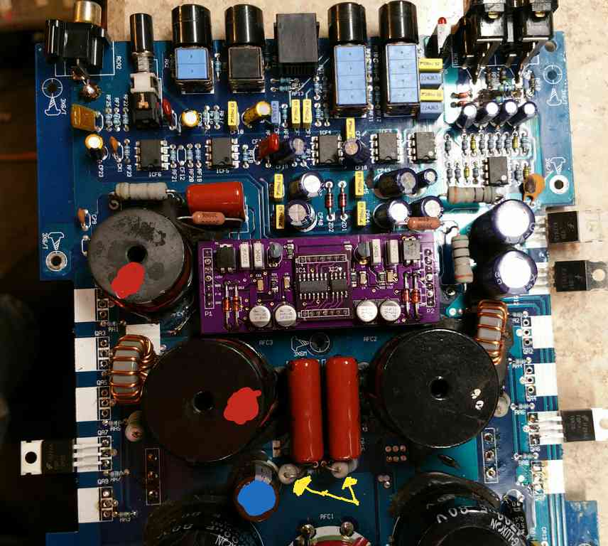
I'm attaching a few more pictures. The first one is just to show where the broken traces were. It looks like that black fixative became corrosive. You can see how loose this inductor is in the picture. The second picture is the same as above, but I marked it up a little. The inductors with red dots are ones that are currently loose from the board. The cap with the blue dot was one I replaced because the original one had vented, and the power resistors that the yellow arrows point toward are getting very how when the amp is under power with a pair of outputs in.
I'm sorry I get so long winded. Any help is sincerely appreciated.
Thanks,
Jason
A few notes I didn't include above because I got sidetracked. First off, the high frequency whine I get out of this after I put a pair of outputs in is audible from one of the output inductors before the muting relay pulls in. When the relay engages it can be head from the speaker as well.
I briefly tried twisting and pulling on the loose inductors, no change, but I did not have a lot of time to try.
This is the amp that had a lot of the input section burned away. I did check and I do have clean audio at the input on the DLM board, so I am thinking it is not a preamp issue.
The reason I am thinking it is a output filter issue is mainly because the frequency of the whine is much higher than anything the amp should be able to pass. We are talking at the upper ranges of average hearing. Probably ~15kHz. I know I didn't like it, and my dog liked it less!
Do any of you have a schematic of a similar style output filter. I did not have time to take a bunch of detailed pictures, but it appears it has 5 different output inductors, not to mention some big ceramic caps and a single electrolytic.
I'm attaching a few more pictures. The first one is just to show where the broken traces were. It looks like that black fixative became corrosive. You can see how loose this inductor is in the picture. The second picture is the same as above, but I marked it up a little. The inductors with red dots are ones that are currently loose from the board. The cap with the blue dot was one I replaced because the original one had vented, and the power resistors that the yellow arrows point toward are getting very how when the amp is under power with a pair of outputs in.
I'm sorry I get so long winded. Any help is sincerely appreciated.
Thanks,
Jason
- Status
- Not open for further replies.
- Home
- General Interest
- Car Audio
- Autotek Mean Machine MX1500.1