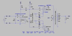
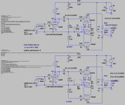
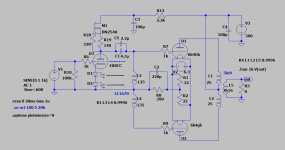
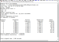
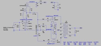
Which one would you go for, in these close to identical circuits? One with LL autoformer and the other with an AC-coupled 1:1+1 transformer. I am only interested in AC-coupling, ie no DC through the primary. Not sure of LL transformer to choose, capable of handling the high signal voltage? Circuit will work between 300Hz and 4kHz.

I agree, even if I am charmed by the simplyness of the latter.
I guess we are talking 1667-1668? Thought of those too, as I have a 1667 5mA lying around to test with.
The only problems with those are that they are bulky compared LL1670, allthough I have not seen it in use as autoformer.
As the amp will work with a limited bandwith, I will hopefully have no bottom or HF problems.
When one sims them they both shows bottom and HF peaks, even if the autoformer gets a higher HF. Might be better with proper loading.
Great to hear this from someone who actually tried LL1670 in this configuration. I guess you removed C2 to enhance balance? Did you notice any big improvements when doing so. What driver did you use? Have E88CC, 5842, 6C45 and a few others in my stash. Might save the E280F for a SE working from 300 and up with horns. The PP is for 414-8E in closed or reflex from 60Hz.
Attachments
Last edited:
Another option might be to consider using the transformer to split phase at the input. Admittedly you then need a 2nd input tube to amplify each phase, but you can keep the AC coupling to the output tubes. And with smaller circa 0.1uF or 0.2uF coupling caps. Works very well in my experience.Which one would you go for, in these close to identical circuits? One with LL autoformer and the other with an AC-coupled 1:1+1 transformer. I am only interested in AC-coupling, ie no DC through the primary. Not sure of LL transformer to choose, capable of handling the high signal voltage? Circuit will work between 300Hz and 4kHz.
View attachment 1367965
My 2 cents, ymmv etc etc
Yes, was into that too, but unfortunately get indcations of high H3.Another option might be to consider using the transformer to split phase at the input.
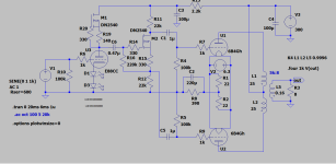
Found the alternative to autoformer, gives the same results with just a minor higher H2 than that. Would have been nice with direct coupling from the input tube but Ua is to high at 150V. Taking the the lower output from below the source resistor actually sims best. A depletion mosfet with lower input capacitance would be desirable, though.
Last edited:
I just check my spice schematic, my C2 is in ultra-path connection, not grounded cathode connection.Great to hear this from someone who actually tried LL1670 in this configuration. I guess you removed C2 to enhance balance? Did you notice any big improvements when doing so. What driver did you use? Have E88CC, 5842, 6C45 and a few others in my stash. Might save the E280F for a SE working from 300 and up with horns. The PP is for 414-8E in closed or reflex from 60Hz.
In additional to LL1670, I have custom-made Nickel core "autoformer" (~150H)
which is an improvement sound-wise over LL1670.
I tried many many drivers: ECC88, DA3, 7119, ECC81. Dual ECC81 (8mA each CCS loaded) is my pick.
Some invariants (A2900, ECC801S) of ECC81 are particularly enjoyable as push-pull drivers.
I just acquire some components to try fixed-bias center choke.
Spice simulation is done but not yet implemented.
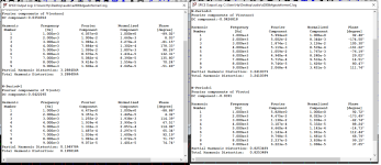
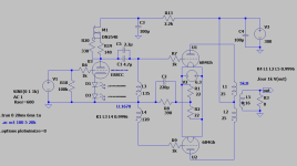
Played around in LTSpice and to my surprise, distortion figures got significantly lower with less inductance in the lower part of the autoformer. More inductance in the upper made results worse. Checked overtone and it seems H2 is the one that is lowered,
Any theories or explanations? My guess is distortion cancellation.
Any theories or explanations? My guess is distortion cancellation.

Attachments
Last edited:
Hi, might have lost the link?Have you read this yet?
Clearly this must be, due to distortion cancelling only affects H2. Did the same operation with the concertina, where the lowest H2 is at 15k/17k anode/cathode resistor. In both concertina and autoformer the quota is 1:1.13.
Last edited:
Oops..Have you read this yet?
http://www.pmillett.com/6B4G_push-pull_amp.htm
Dmitry wrote about harmonics manipulation.
https://www.dmitrynizh.com/hf60-dht.htm
Last edited:
Have read them both read them again now. Dmitry’s is the one who actually pinpoints the imbalance issue. Easy to get fooled by THD.
how abut max out put power of this circuit ?6b4g amplification factor is 4 ....this is not headphon amp .Played around in LTSpice and to my surprise, distortion figures got significantly lower with less inductance in the lower part of the autoformer. More inductance in the upper made results worse. Checked overtone and it seems H2 is the one that is lowered,
Any theories or explanations? My guess is distortion cancellation.
View attachment 1368547
- Home
- Amplifiers
- Tubes / Valves
- Autoformer or transformer PI
