I am not sure if this is the right sub-forum, but I couldn't find anything better, so...
I am looking for a switch that senses the line-level audio signal, switches on an amplifier when there is a signal, and turns the amplifier off when there is no signal for a while. Yes, there is the Rod Elliot #38 circuit, which does exactly that ("Signal Detecting Auto Power-On Unit"). However, I am too lazy to make a PCB for it. I was hoping to find a complete board somewhere, but so far I couldn't.
Any hints or suggestions?
Try calling it an AC detect relay. I've used those in industry, but after the great bankrupcy of US manufacturers, no point in calling out the brand. Followed by a delay-on-off relay. You can use one contact of the AC detect relay to trigger the delay-on-off relay, The delay-on-off relay runs the line AC voltage to your transformer.
These usually plug into octal sockets or similar 11 pin sockets with screw terminals. Don't solder the mains AC voltage, put the wires under screws. Crimp fork terminals can make that easier.
I used an aC detect relay to turn on the heaters on the assembly line x minutes before startup. The clock based timer kept being turned off over the weekend and getting out of sync. So I installed a PDA with internal battery clock, and wired the beeper to the AC detect relay.
Last edited:
I am not sure I understand this. I googled for AC detect relay, but I believe I did not find the right thing. Can you provide a link?
If you know the algorithm of the automation device, it can be developed on discrete elements, IC, relays, solid-state relays or Arduino. You will also need a standby power supply in STB mode.
Found the datasheet on the AC detect module. Action Pak model 1601 for dial turn level, relay closed when AC higher than level, open when lower. Action Instruments 6601 Aero Dr Sn Diego CA 92123. Printed in USA December 1988
If you want the amp to stay on for a while, say between tracks of a record or CD, then you need another relay say a Potter Brumfield delay-on-off timing relay. ActionPak AC detector relay energizes input of delay relay, delay relay closes contacts from AC source to Amp power.
Oddly, ebay has some of these ActionPak modules used available.
Plenty on eBay, like this one: Audio Signal Detecting Auto Power On/Off with Trigger out. ASD-1M or 2M For DIY | eBay
helloy guys
I just found thi on the WWW
https://oshwlab.com/guest/Audio_Detector_Switch-yYuM4mfxP
Would this work? I am planing to use only one channel from front and center for 2nd power supply.
I just found thi on the WWW
https://oshwlab.com/guest/Audio_Detector_Switch-yYuM4mfxP
Would this work? I am planing to use only one channel from front and center for 2nd power supply.
Attachments
I, too, would like some of these! Seems odd that there’s not an off-the-shelf solution.
If you have, say, a small echo dot with the auxiliary out going into a proper amplifier and speakers… you want one of these so that the amplifier is not running 24 hours a day all year!
I’m amazed that there is not somebody selling a plug in semi-smart switch by the bucket load.
If you have, say, a small echo dot with the auxiliary out going into a proper amplifier and speakers… you want one of these so that the amplifier is not running 24 hours a day all year!
I’m amazed that there is not somebody selling a plug in semi-smart switch by the bucket load.
This? https://www.cowlacious.com/audio-activated-switch/
Fell over it a little while ago while looking for something else. No experience with it and not enough knowledge to judge quality of design and implementation...
Fell over it a little while ago while looking for something else. No experience with it and not enough knowledge to judge quality of design and implementation...
Thank you for your reply!
Yes, that’s kind of the thing. I’ve also remembered that I bought something similar a few years back for a different project, but it has no delay/latch on.
This one does:
https://cebek.co.uk/Item/cebek-pm-16-audio-signal-control-relay-switch-microphone-timer-latching
But again… while I have the skills etc to wire it up, put it in a box, I’m left surprised that no one in the world is making a ready to roll, plug in solution!
I guess I’m doing a bit of diy again then!

Maybe this will meet your needs.I’m left surprised that no one in the world is making a ready to roll, plug in solution!
MCM Custom Audio Automatic Two-Way Source Selector - Sound Activated - 50-8396
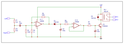
This is how post #12 is supposed to work.
Just explanation, not a recommendation.
R1, R2 average the left and right channel inputs.
C1, R3 block off any DC below 16Hz before entering U1.1.
U1.1 amplifies the input signal by 100x, determined by R5/R4.
You can change detection threshold by changing R5.
Any positive output from U1.1 >0.6V will pass through D1 and charge up C2.
R6, U1.2 is a buffer to charge up the integrator R7/C3.
You can change the delay time by changing R7.
When the integrator output is larger than 0.6V, Q1 will turn on the relay, which e.g. can be the power to the amplifier.
Patrick
There are (at least) 3 issues as i can see :
1. The opamps are powered by single rail, but the input to U1.1 is not protected against signal below Gnd. At least a clamping diode is required.
2. Output of U1.1 needs some current limiting (e.g. resistor) when charging into C2.
3. When the input signal is off, C2 can only discharge through its own leakage current, the leakage current of D1, and the input current of U1.2. It may take a long time to switch off. A large value resistor in parallel will help.
Some people did say the LM358 has internal clamp diodes, but I would still play safe :
https://www.eevblog.com/forum/beginners/protecting-op-amp-input-from-negative-voltages/
Best to simulate in LTSpice first before trying in hardware.
Patrick
Last edited:
- Home
- Amplifiers
- Solid State
- Auto sensing on/off switch