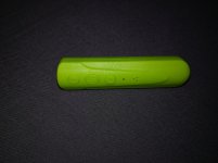
I am looking for a way to hard wire this cheap eBay Bluetooth receiver to my car. You have to press the middle power button (also call answer button) for 3 seconds to power it up. It has a built in battery so needs to be charged via USB. What I would like to do is have this powered on with the car radio 12v remote wire without having to press the power on manually each and every time I get in the car. I would also like it power off with the car stereo.
Can someone help me with a circuit using transistor to help me achieve this. Bearing in mind, I would still like the call answer feature to also work. A capacitor and resistor across the switch may work but will short out when answering calls. I think this may be able to be achieved with a transistor. Any help appreciated.
Can someone help me with a circuit using transistor to help me achieve this. Bearing in mind, I would still like the call answer feature to also work. A capacitor and resistor across the switch may work but will short out when answering calls. I think this may be able to be achieved with a transistor. Any help appreciated.
Attachments
Hmm... is your original idea like this?

And your issue is that when you press the switch the capacitor discharges and the 3 second timer is reset again.
Try this

Set the RC for charging to maybe 5 seconds. The RC for the discharging capacitor can be 30 seconds or anything. You may want an overriding switch just in case tho.
And your issue is that when you press the switch the capacitor discharges and the 3 second timer is reset again.
Try this
Set the RC for charging to maybe 5 seconds. The RC for the discharging capacitor can be 30 seconds or anything. You may want an overriding switch just in case tho.
Hi am not sure I quite follow. I know this can be achieved like this:
Hacking the Link Bluetooth receiver for auto-on and off
But this is not the proper way and has given people issues as per the comments section on that page. I wanted to achieve this using a transistor as a switch and capacitor for momentary latch. For the button side of the device, I need the latch to stay on for 3 seconds only and unlatch automatically after 3 seconds.
As for the power side of the device, I plan to remove the internal battery and replace it with a cap and power the device using the 12v remote feed coming from the car stereo. This way it will go off when the radio is switch off.
Last edited:
As for the power side of the device, I plan to remove the internal battery and replace it with a cap and power the device using the 12v remote feed coming from the car stereo.
Just to clarify, obviously stepping the 12v car battery voltage down to 3.7v
You're thinking of this?

And actually that circuit has a problem... if the PMOS is conducting then the capacitor will never charge, so a resistor is needed to limit the current through the PMOS. But if you put a resistor in series with the PMOS then you risk voltage drop across the resistor + voltage drop across the MOSFET and the resulting voltage seen at the chip's input may be above what it considers as "grounded".
Without knowing the actual circuit, it's hard to tell what to do.
Last edited:
Thanks for your efforts nevertheless. I was thinking more like a transistor switching on to latch/close the devices push switch for 3 seconds and then switching off once a capacitor has charged. Somewhere along those lines.
You will find something to solve your requirement here:
www.electronics-tutorials.ws/waveforms/555_timer.html
www.electronics-tutorials.ws/waveforms/555_timer.html
... using transistor .....
Why do you want a transistor??? They are fragile. They never do what you want.
Cap and relay. Car off, cap goes to zero volts. Switched +12V comes high, cap holds zero V and relay clacks. About 50mS later, cap charge has decayed enough for relay to un-clack. (Alternate use of that same button not inhibited.)
The relay will also clack when car and Switched +12V goes off. I doubt that is a problem.
The first suitable relay I found (TE PCJ-112D3M 301) is $2. Made for PCB but only 4 pins so super-easy to hay-wire, cap and wires wrapped and soldered to relay pins.
Attachments
- Status
- Not open for further replies.
- Home
- General Interest
- Everything Else
- Auto on circuit for Bluetooth receiver