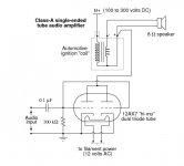
I stumbled across the following link, using an automotive ignition coil as an output transformer Vacuum Tube Audio Amplifier | Discrete Semiconductor Circuits | Electronics Textbook I first thought that the use of an autotransformer in the form of an ignition coil was heresy, but have found many credible links on the subject (including several in this forum) Ignition coil as SE OPT https:/ Placing autotransformer in crossover /jensen-transformers.com/wp-content/uploads/2014/09/Audio-Transformers-Chapter.pdf EDCOR - Isolated Transformer vs. Auto Transformer https://www.diyaudio.com/forums/tubes-valves/ https://forum.audiogon.com/discussions/how-do-autotransformers-affect-sound 105577-output-autotransformers.html https://www.communitypro.com/sites/default/files/Autoformer Tech Note_v2.pdf Ignition Coil Toobe Amplifier
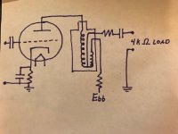
However these links did not answer all of my questions, so I have redrawn the circuit in the typical form of the data sheets for resistance-coupled amps, adding the typical capacitor between Ebb and load, and showing the internal coil resistance as a resistor.
1. The coil has a 100:1 turns ratio, so the reflected load from speakers of 4 Ohms would be 40k Ohms. The coil has DC resistance of 10k Ohms from either + or - terminals to the high tension output. When drawing the load-line are these just added for a total of 50k Ohms ? If we use two tubes in parallel as the original posting shows the output load should be cut in half, so we would draw the load-line for 100k with two tubes in parallel?
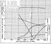
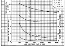
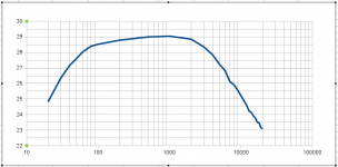
2. This load is abnormal for pentode or triode power tubes. The pentode curves typically show an increase in harmonic distortion as the load increases beyond optimum, but triodes do not (attached images). Therefore is it essential to drive this high load with a triode?
3. The response curve for a typical coil was previously measured and published on this forum (attached). While the response suffers at low and high frequencies, it looks quite good from 60 Hz to 4k Hz. As long as I bi-amp and drive the tweeter with a separate amp and transformer, is there any reason to expect poor fidelity in the 60-4k Hz range?
This actually suits an amp I had planned to build for a car-guy who likes opera. My plan was to move the crossovers out of the human vocal range, with a "main" driver from 60Hz to 4000, a self-powered sub-woofer below, and bi-amped tweeter above. The top-mounted anodes of an 829B would look cool tied to the HT side of the coil !
4. Is the usual Rg resistor required when the load is so low?
Note that the original author acknowledges safety issues with the circuit (high voltage to the speakers), which could presumably be solved with capacitive coupling of the load.
However these links did not answer all of my questions, so I have redrawn the circuit in the typical form of the data sheets for resistance-coupled amps, adding the typical capacitor between Ebb and load, and showing the internal coil resistance as a resistor.
1. The coil has a 100:1 turns ratio, so the reflected load from speakers of 4 Ohms would be 40k Ohms. The coil has DC resistance of 10k Ohms from either + or - terminals to the high tension output. When drawing the load-line are these just added for a total of 50k Ohms ? If we use two tubes in parallel as the original posting shows the output load should be cut in half, so we would draw the load-line for 100k with two tubes in parallel?
2. This load is abnormal for pentode or triode power tubes. The pentode curves typically show an increase in harmonic distortion as the load increases beyond optimum, but triodes do not (attached images). Therefore is it essential to drive this high load with a triode?
3. The response curve for a typical coil was previously measured and published on this forum (attached). While the response suffers at low and high frequencies, it looks quite good from 60 Hz to 4k Hz. As long as I bi-amp and drive the tweeter with a separate amp and transformer, is there any reason to expect poor fidelity in the 60-4k Hz range?
This actually suits an amp I had planned to build for a car-guy who likes opera. My plan was to move the crossovers out of the human vocal range, with a "main" driver from 60Hz to 4000, a self-powered sub-woofer below, and bi-amped tweeter above. The top-mounted anodes of an 829B would look cool tied to the HT side of the coil !
4. Is the usual Rg resistor required when the load is so low?
Note that the original author acknowledges safety issues with the circuit (high voltage to the speakers), which could presumably be solved with capacitive coupling of the load.
Attachments
A vehicle ignition coil has a resonant frequency or optimum efficiency point of around 10kHZ.
A bit high for an audio transformer.
A bit high for an audio transformer.
That "Increase of harmonic distortions" shows that the stage starts clipping when it's amplification factor increases. In order to get the actual picture you must decrease input voltage to the stage while increasing the load resistance. Who drew that pictures in datasheets, and what was their purpose? 😀
Maybe if your deserted on Gilligan's Island ...and you need to rig something up from left over parts.... other than that it is very lossy and limited...
Based on this idea you could use a 120/240V - to 12 (or whatever) Volt mains transfo for PP output with low voltage/impedance- or paralleled power tubes (6C41, 6C19, etc).
Its response probably won't be much worse than the ignition coil's....
Its response probably won't be much worse than the ignition coil's....
Hmmm..... Bug is implanted 🙂 I have some 30 pieces of 6C19-s lying around waiting for their fate 😎
You can make a plane out of paper ... and it will fly.
You can make a cannon and projectile out of a Pringles can and a potato, then shoot it a few yards away.
Both are fine to explain the working principle to an otherwise bored class.
Same here.
You can make a cannon and projectile out of a Pringles can and a potato, then shoot it a few yards away.
Both are fine to explain the working principle to an otherwise bored class.
Same here.
Hmmm..... Bug is implanted 🙂 I have some 30 pieces of 6C19-s lying around waiting for their fate 😎
A 50VA 115+115:6+6 toroidal mains transformer should be ideal for 2 x 6C19P
Use a bypassed CCS in each cathode to balance . You may find that delivering the required grid volts from the 6C19P HT from the driver stage to be an issue .
316a
Let me see it from the other end....😉 You can buy a japanese hand-wound pure silver OPT on permalloy core, beeswax gold foil capacitors, and NOS WE 300B-s for thousands of dollars, and you and you might still end up with something not delivering what you've expected from it.... 😱You can make a plane out of paper ... and it will fly.
You can make a cannon and projectile out of a Pringles can and a potato, then shoot it a few yards away.
Both are fine to explain the working principle to an otherwise bored class.
Same here.
At least the first option is fun to try, and maybe you waste only the cost of a romantic dinner.
DIY-ing in most cases is about trying new ideas -even if they don't always work out well- not chewing your nails agonizing on what and how will work out (or not). I think. 😎
A 50VA 115+115:6+6 toroidal mains transformer should be ideal for 2 x 6C19P
Use a bypassed CCS in each cathode to balance . You may find that delivering the required grid volts from the 6C19P HT from the driver stage to be an issue .
316a
Use two toroids in series to vastly improve LF response, Triad VPT12 or VPT18 are excellent, and can deal with a few mA of DC.
Use a DC boost converter for the HV required by the driver.
I have to wonder how this sort of transformer option would work with a somewhat lower driving impedance. I would likely use it with some sort of powered subwoofer.
I just love the idea of proudly displaying a pair of ignition coils with some sort of directly heated tube.
Maybe I would have to resort to tri-amp with a hand wound torroid on the top end.
I just love the idea of proudly displaying a pair of ignition coils with some sort of directly heated tube.
Maybe I would have to resort to tri-amp with a hand wound torroid on the top end.
Well, if there is one type of application this idea is not really suitable for, then it is a powered subwoofer amplifier....🙁 There you need lots of power and drive capability (current), and these are not the strong points of this topology.
If you did use it, it would have to be used with a high plate resistance device...such as a pentode..or KT or Beam tube... The winding resistance is extremely high and would therefore be added in to the plate resistance when analyzing..
How many milli-watts do you consider enough for subwoofer duty? 😕I have to wonder how this sort of transformer option would work with a somewhat lower driving impedance. I would likely use it with some sort of powered subwoofer.
I just love the idea of proudly displaying a pair of ignition coils with some sort of directly heated tube.
Maybe I would have to resort to tri-amp with a hand wound torroid on the top end.
> Placing autotransformer in crossover /jensen-transformers.com/wp-content/uploads/2014/09/Audio-Transformers-Chapter.pdf EDCOR - Isolated Transformer vs. Auto Transformer https://www.diyaudio.com/forums/tubes-valves/ 105577-output-autotransformers.html
Several of these links are for "auto-transformer".
This is NOT the same as (is more general than) an automobile spark auto-transformer.
Any time you need a low (<3) ratio and do not need isolation, an autotransformer is a buck cheaper and an octave wider band.
Spark-coils were typically 3-wire auto-transformers (two wires and case), but this was to save under-hood wiring.
My impression of spark-coil parameters is they have pee-poor bass response. Also this being the Tubes section, I worry about B+ getting on a load.
But yeah you can get "audio" through these; indeed most iron-core coils.
Last edited:
Yes, I included non-automotive links in an attempt to provide some credibility to the use of autotransormers, at least in non-automotive forms. I assume that an ignition coil is not the best of the lot. However the coils in my garage are heavier than many of the output transformers I have used so they were not stingy with the core. I tend to buy transformers by the pound, assuming a correlation between mass and bass response and power.
I assume capacitive coupling would address the issue with B+ on the load? Even a pair of caps could be used in series in case one died.
The lack of bass could be addressed with a traditionally driven sub-woofer.
But the high reflected load provides a flat load-line. What are the known issues and opportunities associated with flat load-lines?
- Status
- Not open for further replies.
- Home
- Amplifiers
- Tubes / Valves
- Auto ignition coil as output transformer