There have been in the past several thread split off's, all dealing with finding answers to the mysteries of MM Carts.
Topics were level dependency of linearity, interaction with the LP, type of mechanical resonance, reason for a dip at 10kHz that most Carts have, etc ,etc.
Since many designs are spread all over these various threads, the idea of this thread is to keep those designs together and not so much as a discussion thread.
Please see it as an technical addendum to the thread "Cartridge Dynamic Behaviour"
One of the tools used for investigation has been the so called Aurak preamp that LD or Luckythedog brought forward.
This a phono amp that goes one step further as replacing the 47k termination resistor by a much lower value of ca 10k creating a 75usec pole.
The advantage of doing such things is that the influence of cable capacitance on the FR becomes much lower, thereby coming "closer" to the sound that the Cart is producing.
The Aurak preamp takes this even one step further by offering a virtual gnd input to the Cart, a so called transimpedance amp with neglectable sensitivity for cable influences.
In principle the FR of an Aurak goes quite a bit beyond that of the 47k//200pF type of preamp, a big advantage when investigating the supersonic properties.
When using a transimpedance amp, a pole is created at Rc/(Lc*2Pi) Hz, resp the inductance and resistance of the Cart, usually somewhere between 100Hz and 300Hz.
This pole has to be corrected to get the Riaa curve as needed.
The basic Aurak version therefore asks to add a resistor in series with the the Cart, who's values is 2*Lc(mH)-Rc. Example: for a 450mH/ 750 Ohm Cart, 150 Ohm has to be added.
This boils down to creating a pole with a 500usec time constant. Internally the Aurak shifts this pole to 75usec, being T3 of the Riaa curve.
Now a second amp stage is still needed for only the 3180usec and the 318usec Riaa time constants, resp called T1 and T2.
There are cases however that the math of this basic version with 2*Lc-Rc is giving a negative result. In that case 3L-R or 4L-R can easily be achieved by modifying the internal correction network.
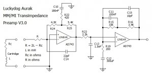
The image below shows the basic Aurak. First stage shifts the 500usec pole to 75usec. The second stage takes care of T1 and T2 that Riaa prescribes.
Between the two stage is visible a fourth filter, 2k2//1n5. This is optionally the unofficial T4 timeconstant of 3.15usec, creating a pole at 50kHz.
More to follow.
Hans
Erratum:
A somewhat cryptic formulation in the above text might possibly lead to a misunderstanding.
The false impression could have been given that in the Aurak the usual 47K terminationresistor was replaced by a 10K resistor, but that's of course not at all the case.
The intention was to showing several ways how to connect an MM Cart to a preamp along a timeline going from:
1) The original 47k termination, to
2) Attempts by some to reduce the effects of cable capacitances from Cart to preamp, by replacing this 47K with a ca. 10k termination, thereby creating a 75usec pole (f.i. Barney Oliverand Bob Cordell) and
3) A transimpedance as a next step, such as this Aurak, where the Cart is connected to a virtual gnd, completely differing from step 2.
Topics were level dependency of linearity, interaction with the LP, type of mechanical resonance, reason for a dip at 10kHz that most Carts have, etc ,etc.
Since many designs are spread all over these various threads, the idea of this thread is to keep those designs together and not so much as a discussion thread.
Please see it as an technical addendum to the thread "Cartridge Dynamic Behaviour"
One of the tools used for investigation has been the so called Aurak preamp that LD or Luckythedog brought forward.
This a phono amp that goes one step further as replacing the 47k termination resistor by a much lower value of ca 10k creating a 75usec pole.
The advantage of doing such things is that the influence of cable capacitance on the FR becomes much lower, thereby coming "closer" to the sound that the Cart is producing.
The Aurak preamp takes this even one step further by offering a virtual gnd input to the Cart, a so called transimpedance amp with neglectable sensitivity for cable influences.
In principle the FR of an Aurak goes quite a bit beyond that of the 47k//200pF type of preamp, a big advantage when investigating the supersonic properties.
When using a transimpedance amp, a pole is created at Rc/(Lc*2Pi) Hz, resp the inductance and resistance of the Cart, usually somewhere between 100Hz and 300Hz.
This pole has to be corrected to get the Riaa curve as needed.
The basic Aurak version therefore asks to add a resistor in series with the the Cart, who's values is 2*Lc(mH)-Rc. Example: for a 450mH/ 750 Ohm Cart, 150 Ohm has to be added.
This boils down to creating a pole with a 500usec time constant. Internally the Aurak shifts this pole to 75usec, being T3 of the Riaa curve.
Now a second amp stage is still needed for only the 3180usec and the 318usec Riaa time constants, resp called T1 and T2.
There are cases however that the math of this basic version with 2*Lc-Rc is giving a negative result. In that case 3L-R or 4L-R can easily be achieved by modifying the internal correction network.
The image below shows the basic Aurak. First stage shifts the 500usec pole to 75usec. The second stage takes care of T1 and T2 that Riaa prescribes.
Between the two stage is visible a fourth filter, 2k2//1n5. This is optionally the unofficial T4 timeconstant of 3.15usec, creating a pole at 50kHz.
More to follow.
Hans
Erratum:
A somewhat cryptic formulation in the above text might possibly lead to a misunderstanding.
The false impression could have been given that in the Aurak the usual 47K terminationresistor was replaced by a 10K resistor, but that's of course not at all the case.
The intention was to showing several ways how to connect an MM Cart to a preamp along a timeline going from:
1) The original 47k termination, to
2) Attempts by some to reduce the effects of cable capacitances from Cart to preamp, by replacing this 47K with a ca. 10k termination, thereby creating a 75usec pole (f.i. Barney Oliverand Bob Cordell) and
3) A transimpedance as a next step, such as this Aurak, where the Cart is connected to a virtual gnd, completely differing from step 2.
Attachments
Last edited:
Thank you Hans for the initiative to build a home for the Aurak.
Thanks to seven lines of text you wrote, I feel like I am a bit more of an advanced monkey, pretending that I now understand the mysterious peculiarity of this LD’s design, which I have built and enjoy.

George
Thanks to seven lines of text you wrote, I feel like I am a bit more of an advanced monkey, pretending that I now understand the mysterious peculiarity of this LD’s design, which I have built and enjoy.
George
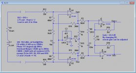
Emerged from the SE version came the differential Aurak version.
Making a differential amp with two voltage amps, leads to a penalty in noise contribution.
However, doing the same with transimpedance amps does exactly the opposite, giving a 3dB noise bonus.
A differential amp when working properly, should have a high CMRR where a SE version has no CMRR at all.
This should bring a big benefit in preventing gnd loops an suppression of EMI signals being picked up from the surrounding atmosphere.
However the Cart's 4 output signals should have no connection to mains gnd and ditto for the cabling, presenting a potential problem to some.
The differential design is in the image below.
Hans
Attachments
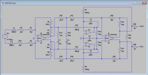
Then Billshurv found a complete PCB from Russ White that could be easily transformed into a differential Aurak.
Lo-Z boards available from Retro - Balanced RIAA Stage
This design is based on the OPA1632, a differential amp to start with, with favourable specs.
With this design, the CMRR depends less on the tolerance of the used resistor values.
Overall Gain can be changed with R24 and the Math R=2Lc-Rc can also be changed easily by changing R3-R6, where the sum of R3-R4 resp. R5-R6 should always stay 88K3.
Hans
Attachments
Not quite, but close...…….!One of the tools used for investigation has been the so called Aurak preamp that LD or Luckythedog brought forward.
This a phono amp that goes one step further as replacing the 47k termination resistor by a much lower value of ca 10k creating a 75usec pole.
The advantage of doing such things is that the influence of cable capacitance on the FR becomes much lower, thereby coming "closer" to the sound that the Cart is producing.
The single ended Aurak 3.0 sketch in the OP is a preamp I came up a few years ago now as a means to avoid effects of the LCR resonance in MM carts. I've been using it as my main listening preamp since then, wouldn't swap it.
My Aurak 3.0 SE (single ended) design shown in the OP is a true transimpedance preamp. It has input impedance of 0.1ohms@100Hz, 3.2ohms@1kHz and 63ohms@10kHz.
There is no series 10k or so resistor. Aurak does not directly form the 75uS time constant from the preamp's input impedance and cartridge inductance, but the 1st stage does implement the 75us RIAA pole with a nice trick.
IMO the single ended version is fine and performs well. There's no need and not much advantage of a balanced version, which has disadvantage of requiring re-wiring of the headshell/arm. The SE version works with standard wiring and is relatively easy to build and try.
The point of Aurak is that it doesn't have the relatively high value series resistor of the Barney Oliver class preamps: it is a true transimpedance design. This is how Aurak eliminates the MM/MI LCR resonant system.
Just be careful what you wish for...…………..(!)
LD
Last edited:
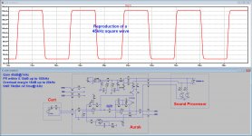
And the latest reincarnation is a universal SE Aurak.
This version can be used in combination with a sound processor, in that case also receiving it's power through the phantom XLR connection.
But it can also be used independently, either needing +/- 9V from batteries or from a mains supply.
Because phantom only produces a positive supply, the negative supply is made on board with a simple low cost switched capacitor converter.
This converter operates at 50kHz, far away from audio, but still not producing the EMI interference from a buck converter.
And because of this converter, it is also possible to feed the circuit from a single positive supply when no sound processor is being used. All options are open.
This Aurak is again realised using two stages. The first stage shifts the pole from cart plus resistor from 500usec to 75sec when using the R=2*Lc-Rc math.
The second stage takes care of T1 and T2.
To improve SNR I have increased gain of the first stage by 20dB and transferred the 3.18usec filter to the second stage.
A strap can switch this option on and off.
Because the original Rg in the second stage (200 Ohm) is part of T1 and T2, I have rearranged the inputs, now with Rg as a direct input from the first stage.
The benefit is that this resistor can be changed when a different overall gain is needed, without having to recalculate the filter component.
Op amps used are the OPA1642, very fast low noise Fet duals that only consume ca. 2mA/amp low enough to be powered by the Phantom line.
A servo was used keeping offset in the mV range.
When using a sound processor, it will be possible to choose between the output from the first stage and do the remaining time constants digitally, or take the second stage without the need of further processing.
In a next posting I will make a calculation available, making use of Excel, when the 2*Lc-Rc does not fit.
Hans
Attachments
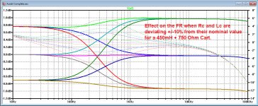
Tuning tip nr1:
In the more usual situation with a 47K termination load, the exact figures for Lc and Rc as provided by the manufacturer are almost meaningless.
But, in case of this Aurak preamp, Lc and Rc are part of the equation to create a pole, like 500usec in case of using R = 2*Lc - Rc.
In the image below is shown that a variation of 10% in Lc or Rc from nominal may lead to a FR deviation of 2dB, for a region where our auditory system is most sensitive.
However, the remedy is quite simple. When playing a test LP, the FR can be flattened by changing the value of R while looking at the region between 20 Hz and 2kHz, that's all.
Hans
Attachments
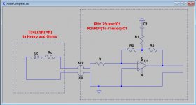
Calculation of components of Aurak stage 1.
Here is a quick way how to calculate the various components in the first stage, see image below.
With an L and R, we can make a second order low pass filter who's corner frequency is at 1/(Tc*2Pi), where Tc= L/R (1)
When using R = 2*Lc-Rc for the calculation of R, Lc is taken by LD in mH and Rc and R in Ohm.
When using Henry and Ohms instead, the math becomes R=2000*Lc-Rc or Lc=(Rc+R)/2000 (2)
Substituting (2) in (1) gives Tc = (Rc+R)/(2000*(Rc+R))= 500uSec (3)
From here let's try to keep things as universal as possible and just consider Ro = (Rc+R)
With a Cart connected to a virtual input Tc=Lc/Ro.
This Tc is not in any way part of the Riaa correction curve, so for the Aurak the choice was made to shift this pole from Lc/Ro all the way up to 75usec, being T3 of the Riaa curve.
This implies that starting from Tc a first order amplication should be applied, ending at 75usec.
The combination of original roll off at Tc and the amplification starting at Tc and stopping at 75usec, results in a low pass filter with a pole at 75usec.
All the second stage has to do is to apply the proper 3180usec and 318usec pole and zero to get the full Riaa curve.
So whatever is attached to the first stage's input, its output should conform to a low pass with a pole at 75usec.
Now to the calculation of components.
The component easiest to start with is C1.
This cap determines to a large degree the gain of the first stage and should be somewhere between 20nF and 200nf. The larger, the lower the gain of the first stage.
Having chosen for C1, R1 follows with R1 = 75usec/C1 (4)
and (R2//R3+R1)*C1 = Tc results in R2//R3 = (Tc-75usec)/C1 (5)
It doesn't matter whether R3 and R4 are equal or different, only R3//R4 counts.
So let's take an example.
The Aurak in posting #1 used the math R = 2*Lc-Rc, or in that case Tc is 500usec as calculated above in (3).
C1 was choosen in that example at 180nF.
Aplying (4) and (5) gives R1=75usec/180nF=417 Ohm.
R3//R4 = (500usec - 75usec)/180nF= 2K36.
The simple way is to take two 4k72 resistors, but it may also be 5K4 and 4k19.
As can be seen in the first posting, all calculated values are almost exact.
When doing the same for the version in posting#6 with a 27nF cap for C1 and also for a Tc=500usec, we get
R1=75usec/27nF=2k78 and R3//R4= (500usec-75usec)/27nF =15k74.
When taking equal versions for R3 and R4, they should be 31K5 each.
This also conforms to the values used.
But it makes it also quite clear that there is no need whatsoever to take 500usec for Tc.
When not having the desire to frequently change between Carts, you can simply take the extra R out of the equation and connect the Cart directly to the virtual input.
For instance, when having a 450mH + 700 Ohm Cart, Tc becomes 0.45/700= 643usec.
Now again with a 27nF cap for C1, R1 (= 75usec/C1) stays at 2k78, but R3//R4 now becomes (643usec-75usec)/27nF= 21k.
With two equal values for R3 and R4 they can each be 42K, or 47k + 38K or whatever gives 21k when paralleling.
Hans
Attachments
Last edited:
A feature of the above circuit is that the opamp does not need to be unity gain stable, depending on the R3/R1 ratio
The simple way is to take two 4k72 resistors, but it may also be 5K4 and 4k19.
As can be seen in the first posting, all calculated values are almost exact.
Not exactly, the error is very small but the two resistors fall out of a quadratic equation 5.4K and 4.2K are exact and can be swapped but making them equal gives a slight gain error. You need to be careful any two resistors with the right parallel value definitely do not work without changing the gain which is proportional to the sum which you want to keep equal.
Last edited:
And here is the automated way to select your Aurak components.
Unzip the file and start entering C1, Lc and (Rc+R).
Excel will consequently calculate a value for R1 and for R2//R3.
Its up to you to select a value for R2, Excel will not only calculate R3, but also the gain at 1Khz in dB for this first stage.
To keep SNR low, this gain at 1kHz should preferably be at 30dB or higher.
You can play just as long with the model until you like the result.
Succes.
Hans
Attachments
Last edited:
The bad news is that the transimpedance amplifier must be tuned for each cartridge. The good news is that the tuning only affects the middle of the audio range, where the cartridge resonances are almost non-existent. Therefore, no test LP is needed for tuning. Tuning can only be done electrically. A small resistor (1 ... 10 Ohm) can be provided in the ground wire of the cartridge and a signal from the generator can be applied to it through the anti-RIAA circuit. Next, you need to achieve linearity in the frequency response in the range of 100 Hz - 2 kHz.However, the remedy is quite simple. When playing a test LP, the FR can be flattened by changing the value of R while looking at the region between 20 Hz and 2kHz, that's all.

- Home
- Source & Line
- Analogue Source
- Aurak, technical reference as addendum to Cart. Dyn. Behav.