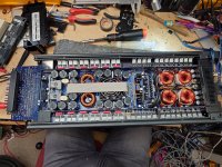
Hi all! Before I strip this down and get too deep into diagnosing, I wanted to check here first for any potential insight or "common issues" on what this amp is doing. It is an LRX 1.2K with no previous repairs, visibly fantastic board condition with no signs of vibration damage, condensation residue, etc.
It powers up, SMPS PWM good, class D switching good, idle current at 12v is 5.8A. Seems high but i'm not sure what is normal for these. Most of that is output section. Nothing getting worryingly hot on the thermal imager.
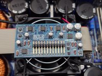
I suspect there is an issue with either the DLD.1 board (as I believe the overcurrent sensing may happen here) or the preamp board. There was a previous thread I saw which mentioned the top-left JFET marked GK on the DLD.1 had something to do with overload muting, I did remove it and powered up but there is no change in behaviour. I also changed the TL072C beside it as a stab in the dark, no change. There are no dead-short semiconductor parts or caps on the board and it all looks visibly good.
Although this is what the amp is currently doing, I want to mention that when i powered it up for the very first time, i DID in fact get audio output, and the overload LED was flashing which the manual suggests is "rare" overcurrent, seems to be more of an indicator as it does not mute output. While powered up initially, regardless of whether I had an RCA in or not, there would be slight "wobbling" voltage on the output terminal, a few mV of DC up and down with no obvious rhythm, and then amp would sporadically disengage the main relays with the orange OL led going solid, and then reset and re-engage the relays. Between this time of initial diagnosis and what the amp is doing now, no changes were made to the circuit and nothing was shorted by a probe, all I did was remove and reseat some of the daughter boards, and the change in behaviour kind of slowly progressed to this current state. In its current behaviour with the audio permanently muted and OL led solid, there is no mV bouncing around at the terminals, which suggests that was coming from the preamp board perhaps.
Any past experience you may have will be appreciated before I spend a lot of time on this! Thanks!
It powers up, SMPS PWM good, class D switching good, idle current at 12v is 5.8A. Seems high but i'm not sure what is normal for these. Most of that is output section. Nothing getting worryingly hot on the thermal imager.
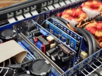
- The main relays engage, but there is no audio output, and the Overload orange LED is lit solidly. From the manual I gauge that audio is muted during this protection mode, and the amp should self-reset and unmute, which it does not. The muting appears to happen on the detachable preamp board as I have no sine wave at any of the header pins to the main board. There is no load attached to the amp at all. This fault is the same whether or not any RCAs are connected.
- With the class D driver card removed (DLD.1) the amp hard-protects with all the LEDs illuminated.
- With the auxiliary supply board removed the amp stays on, 1.3A draw, but of course no class D switching. The orange Overload led is not lit, so I can almost rule out the CPU.1 board being an issue i think.
- With the CPU.1 board removed obviously nothing happens other than the main relays engaging. Green light is on, orange OL light is not.
I suspect there is an issue with either the DLD.1 board (as I believe the overcurrent sensing may happen here) or the preamp board. There was a previous thread I saw which mentioned the top-left JFET marked GK on the DLD.1 had something to do with overload muting, I did remove it and powered up but there is no change in behaviour. I also changed the TL072C beside it as a stab in the dark, no change. There are no dead-short semiconductor parts or caps on the board and it all looks visibly good.
Although this is what the amp is currently doing, I want to mention that when i powered it up for the very first time, i DID in fact get audio output, and the overload LED was flashing which the manual suggests is "rare" overcurrent, seems to be more of an indicator as it does not mute output. While powered up initially, regardless of whether I had an RCA in or not, there would be slight "wobbling" voltage on the output terminal, a few mV of DC up and down with no obvious rhythm, and then amp would sporadically disengage the main relays with the orange OL led going solid, and then reset and re-engage the relays. Between this time of initial diagnosis and what the amp is doing now, no changes were made to the circuit and nothing was shorted by a probe, all I did was remove and reseat some of the daughter boards, and the change in behaviour kind of slowly progressed to this current state. In its current behaviour with the audio permanently muted and OL led solid, there is no mV bouncing around at the terminals, which suggests that was coming from the preamp board perhaps.
Any past experience you may have will be appreciated before I spend a lot of time on this! Thanks!
Attachments
Hi Sam.
Here is dedicated forum section - https://www.diyaudio.com/community/forums/car-audio.38/
There you can find Audison/Hertz tech - https://www.diyaudio.com/community/members/ppalli.33311/ - to save time you can ask him in pm.
Since you have PWM at amps powerstage, yes it does look like there's FET somewhere in between, that mutes the audio. I would track down the audio signal, starting from input buffer stage straight to the amplifiers DC decoupling capacitor/FB resistor divider.
If you have driver/modulator photos - post 'em (just for curiosity).
Last edited:
https://www.diyaudio.com/community/threads/audison-av-5-1k.373836/#post-7503109 - DLD.1 board diagram
So lookin at schematic, DLD-board is a modulator (fullbridge amp) coupled with part of protection circuit.