If you have removed the motherboard from the chassis, it is normal for the current to increase after a while because there is a mute timer acting also on bias regulation and there is no thermal feedback on the power transistors.
Short together the three terminals of the TO92 transistor above the bias trimmer, one per channel, and you will see that the current should be less than 2A.
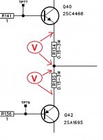
If you still have high current, maybe you have a 'leakage' on driver transistor or power transistor, on one channel: you can check this, measuring voltage directly on output 0.15 Ohm resistor: do this carefully and fast.
Short together the three terminals of the TO92 transistor above the bias trimmer, one per channel, and you will see that the current should be less than 2A.
If you still have high current, maybe you have a 'leakage' on driver transistor or power transistor, on one channel: you can check this, measuring voltage directly on output 0.15 Ohm resistor: do this carefully and fast.

I made a jumper on all four TO-92 transistors. The current increases to 0.56A
and it stops there.
How is it with the heating of transistors outside the housing? Shouldn't they all heat up more or less the same ?? In my case, only 2 channels heat up, but one of them is always stronger. I looked for short circuits on semiconductors with a multimeter, but found nothing. It is a pity that after so many years there is no service instruction anywhere. It would be easier.
The heating of the output transistors will vary by the bias current through them. If you bypass the bias transistor as instructed above, there should be no heating.
Bypassing the bias transistor (in most amps) clamps the driver bias voltage which prevents them from driving the outputs 'on'.
Bypassing the bias transistor (in most amps) clamps the driver bias voltage which prevents them from driving the outputs 'on'.
Thanks for the clarification, Perry. In this case, only one side (two channels) heats up, but one of them more than the other. It is probably as ppalli mentioned that the problem is on the control side.The heating of the output transistors will vary by the bias current through them. If you bypass the bias transistor as instructed above, there should be no heating.
Bypassing the bias transistor (in most amps) clamps the driver bias voltage which prevents them from driving the outputs 'on'.
Without a schematic, it's just a maze. Lots of items and grommets.😒🙁
Last edited:
This is one channel ...
Check voltage across output resistor, because power transistor current must be 0A and ''If you bypass the bias transistor.......there should be no heating'' at all.
The voltage at the output of the emitter resistors is 0V between the AGND.
Do you have a complete LRX 4.300 schematic?
I'm searching....
....'across output resistor': i mean not to AGND, check how many mV you have at the ends of power resistor connected to power transistor that heats up
When the power supply starts the amplifier, the voltage starts to increase rapidly and is 55mV when cut at 3.5A.
3mV in a "good" channel.
- Home
- General Interest
- Car Audio
- Audison LRX 4.300 "safe" mode