Gentlemen,
for reasons of historical interest and sake of completeness
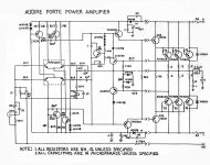
let me offer some Audire schematic diagrams here.
The company owner Julius Siksnius died some time ago and
can no longer be asked. I did repairs for the local distributor
and we received the schematics by letter or Fax - but the scan
quality is not too bad thanks to my lawyer (you know what a
lawyer is good for). These are the "official" factory diagrams,
in pen and ruler style as usual at the time. Hand written
remarks "in English" are from Julius himself.
I am sorry I do not have any preamp schematics except for
model Legato.
The power amps are pretty similar and use the same driver
structure for each model. The only difference apart from supply
voltage and hence power output is the number of output devices
and some adapted parts values.
He did not include schematics of the power amp supplies, these
are simple and do not need any clarification.
Except for standard current limit and supply fuses the power amps
have no protection circuits and speaker relays.
Everybody is invited to share their Audire circuits here, thanks !
for reasons of historical interest and sake of completeness
let me offer some Audire schematic diagrams here.
The company owner Julius Siksnius died some time ago and
can no longer be asked. I did repairs for the local distributor
and we received the schematics by letter or Fax - but the scan
quality is not too bad thanks to my lawyer (you know what a
lawyer is good for). These are the "official" factory diagrams,
in pen and ruler style as usual at the time. Hand written
remarks "in English" are from Julius himself.
I am sorry I do not have any preamp schematics except for
model Legato.
The power amps are pretty similar and use the same driver
structure for each model. The only difference apart from supply
voltage and hence power output is the number of output devices
and some adapted parts values.
He did not include schematics of the power amp supplies, these
are simple and do not need any clarification.
Except for standard current limit and supply fuses the power amps
have no protection circuits and speaker relays.
Everybody is invited to share their Audire circuits here, thanks !
Last edited:

Audire Crescendo Troubleshooting on Audiokarma
https://audiokarma.org/forums/index.php?threads/troubleshooting-help-audire-crescendo-amp.1058283/
https://audiokarma.org/forums/index.php?threads/troubleshooting-help-audire-crescendo-amp.1058283/
A different Legato schematic is here :
https://audiocircuit.dk/downloads/a-other/Audire-Legato-pre-sch.pdf
The one on HiFi Engine looks the same.
https://audiocircuit.dk/downloads/a-other/Audire-Legato-pre-sch.pdf
The one on HiFi Engine looks the same.
Good scan of the Forte circuit, but without balanced input :
Another good scan is on HiFi Engine.
Hi, I am also looking for schematic in hope to fix my old unit.
Kind regards,
-Nader
Another good scan is on HiFi Engine.
Thank you for sharing these historically valuable Audire schematics. Julius Siksnius' handwritten notes add a personal touch, and it’s helpful to know that the power amp designs are structurally similar, differing mainly in output devices and part values. Your explanation about the simple power supplies and lack of protection circuits is also clear and useful.Gentlemen,
for reasons of historical interest and sake of completeness
let me offer some Audire schematic diagrams here.
The company owner Julius Siksnius died some time ago and
can no longer be asked. I did repairs for the local distributor
and we received the schematics by letter or Fax - but the scan
quality is not too bad thanks to my lawyer (you know what a
lawyer is good for). These are the "official" factory diagrams,
in pen and ruler style as usual at the time. Hand written
remarks "in English" are from Julius himself.
I am sorry I do not have any preamp schematics except for
model Legato hair transplant turkey.
The power amps are pretty similar and use the same driver
structure for each model. The only difference apart from supply
voltage and hence power output is the number of output devices
and some adapted parts values.
He did not include schematics of the power amp supplies, these
are simple and do not need any clarification.
Except for standard current limit and supply fuses the power amps
have no protection circuits and speaker relays.
Everybody is invited to share their Audire circuits here, thanks !
Thanks for sharing that info. I'll just mention here for people looking at this in the future: It looks like the Crescendo power amp runs on 46V rails but the quad transistor IC used for the input diff amp has a 40V max VCE (the -A version of the parts gives you an extra 5V for a 45V max) !!
http://matthieu.benoit.free.fr/cross/data_sheets/MPQ6600.pdf

http://matthieu.benoit.free.fr/cross/data_sheets/MPQ6600.pdf
@mlloyd1 - that might have been why those quad input ICs seemed to fail frequently enough that Julius changed out a lot of them for MPS8099/8599, joined on top with high heat adhesive to an aluminum heat spreader.
The early CFP Crescendo schematics (BJT and MOSFET) have never found their way online as far as I can tell, but this is the EF BJT version, single-ended.

The early CFP Crescendo schematics (BJT and MOSFET) have never found their way online as far as I can tell, but this is the EF BJT version, single-ended.
Although not a schematic, potentially of interest to some here...
I have designed new replacement boards for the BJT TO-3 versions of the Noble mono blocks. These were designed with a large aluminum mount bolted to the heat sink. This put the TO-3s directly under the output board. Later, Julius eliminated that mount and installed MOSFETs away from each side of the board, spreading the heat better and removing the hot spot from beneath the output board.
This board fried, possibly from thermal runaway and cascading parts failures. The boards in both mono blocks were so severely damaged I decided against trying to repair them.

This is the new board. Using a two-layer design allowed me to beef up the ground plane, eliminate a jumper, enlarge some traces and pads, and fine-tune the layout.

I have designed new replacement boards for the BJT TO-3 versions of the Noble mono blocks. These were designed with a large aluminum mount bolted to the heat sink. This put the TO-3s directly under the output board. Later, Julius eliminated that mount and installed MOSFETs away from each side of the board, spreading the heat better and removing the hot spot from beneath the output board.
This board fried, possibly from thermal runaway and cascading parts failures. The boards in both mono blocks were so severely damaged I decided against trying to repair them.
This is the new board. Using a two-layer design allowed me to beef up the ground plane, eliminate a jumper, enlarge some traces and pads, and fine-tune the layout.
Yes, with white solder mask.
It was a lot of very careful measuring with digital calipers. Turned out to fit the pins of the output devices more concentrically in the aluminum plate better than the originals.
It was a lot of very careful measuring with digital calipers. Turned out to fit the pins of the output devices more concentrically in the aluminum plate better than the originals.
- Home
- Amplifiers
- Solid State
- Audire USA Amplifier Schematics