Does anyone have or made a schematic for this amp that they could pass along to me?
When powering on, the protection engages the relay to stop passing DC on to the outputs. There is about +50VDC on the emitters of the A1943 & C5200. The rails are around +75VDC & -75VDC. None of the outputs or drivers are shorted or leaking.
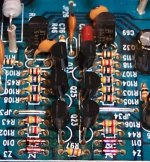
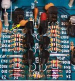
Q30 (2SA1145) & Q32 (2SC2705) get real hot. Picture is the area of concern, with Q30 & Q32 in the back.
When powering on, the protection engages the relay to stop passing DC on to the outputs. There is about +50VDC on the emitters of the A1943 & C5200. The rails are around +75VDC & -75VDC. None of the outputs or drivers are shorted or leaking.
Q30 (2SA1145) & Q32 (2SC2705) get real hot. Picture is the area of concern, with Q30 & Q32 in the back.
Attachments
Hi,
Check the base of the transistors. It would tell you why there is voltage in the emitter. Sometime power transistor check okay statically. When apply load them the they break down. If the base voltage is close to zero and you have voltage in the emitter means one is leaking.
Check the base of the transistors. It would tell you why there is voltage in the emitter. Sometime power transistor check okay statically. When apply load them the they break down. If the base voltage is close to zero and you have voltage in the emitter means one is leaking.
The outputs have the same 50V on the base as on the emitter. The drivers apear to functioning correctly too, they have 50V on both the base and emitters. Something has the throttle cracked open. Driving a signal into the amp, I lose the signal after the op amps.
The picture shows the area I think are between the output drivers and the op amps. Those are 2SC2240's on the left and 2SA970's to the right.
The picture shows the area I think are between the output drivers and the op amps. Those are 2SC2240's on the left and 2SA970's to the right.
Hi,
That's mean that something is driving the driver to go 50 volts. Them check the base of the drivers. Is you have high voltage also you back track what is driving the driver high. I can not help since I do not have the schematic. If the driver are driver directly from the op amp check the output voltage of the op amp.
That's mean that something is driving the driver to go 50 volts. Them check the base of the drivers. Is you have high voltage also you back track what is driving the driver high. I can not help since I do not have the schematic. If the driver are driver directly from the op amp check the output voltage of the op amp.
I have high voltage all the way back to each of those transistors shown in the picture.
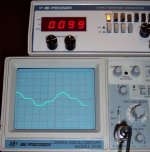
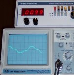
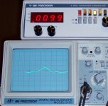
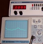
If I unplug the rail supply, the amp will come out of protection and I can see the signal all the way to the output teminals. However, it isn't clean. Here are some pictures of what I am seeing. It apears like something is not allowing the PNP side to develop signal equally to the NPN side.
Is this what should be expected for not having the rail supply connected?
Attachments

That's look like you have ripples in the power supply. Check the rail voltage with the scope. You should see almost straight line in the scope. Do you have an input signal in the input?
Are you feeding a sine wave signal to the input? If that is true then that's is what you should see in the output. I can see the positive and negative side of the signal generated at the driver output but it should be the same as the input.
The first picture of the scope is the sine wave I'm driving into the amp.
The drivers have the same signal as shown in the other four.
These measurements are with just the +/- 15V supplied, as stated earlier the rail supply is disconnected.
The drivers have the same signal as shown in the other four.
These measurements are with just the +/- 15V supplied, as stated earlier the rail supply is disconnected.
Backtrack and check the voltage with the scope the transistors collectors and base of the transistors driving the base of the drivers. Without the schematic is hard to troubleshoot the amplifier. The scope is the best test equipment to troubleshoot. Just follow the path of the input signal and when does not compare you may found what it is causing the problem.
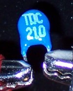
Near as I can tell this is an NTC thermistor.
I removed it from the circuit and measure about 1330 Ohms accross it at room temp. It falls to about 275 Ohms when I hold a soldering iron near it.
Does the marking mean that it should be 210 Ohms at room temp and drop from there OR is it correct that it drops to 210 Ohms as its lowest resistance?
I removed it from the circuit and measure about 1330 Ohms accross it at room temp. It falls to about 275 Ohms when I hold a soldering iron near it.
Does the marking mean that it should be 210 Ohms at room temp and drop from there OR is it correct that it drops to 210 Ohms as its lowest resistance?
Attachments
Found the problem. The 22pF ceramic cap indicated by yellow arrow had failed. I only had 33pF caps on hand and replaced two of the 22pF to keep it balanced (the other one is behind the 2sc2705) The amp works with those, however I think I should put the correct value in there, as it doesn't sound quite right even though the scope on the outputs looks clean.
Attachments
- Status
- Not open for further replies.
- Home
- Amplifiers
- Solid State
- Audiosource AMPSUB210 Help Please