at last.
14.6Vdc when unloaded.
Now you know how much voltage the R of the CRC must drop to arrive at your desired final supply voltage.
If the R is chosen a little (or even a lot) too big, you can add a second or a third parallel resistor to lower the Vdrop.
14.6Vdc when unloaded.
Now you know how much voltage the R of the CRC must drop to arrive at your desired final supply voltage.
If the R is chosen a little (or even a lot) too big, you can add a second or a third parallel resistor to lower the Vdrop.
well, i connected transformer to the circuit and measured the voltage after 20R resistors, 11.6 and 11.8Vdc under load..
finally it's ready to working.. thank you very much for your helps and patience 🙂
naim
finally it's ready to working.. thank you very much for your helps and patience 🙂
naim
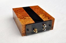

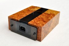
Looks great ! Is that vinyl over acrylic sheet ? Looking at the acrylic strip in the middle it doesn't look like wood on either side !
VERY nicely done !
VERY nicely done !
(Veneer or full block?)
Thank you everybody!
Actually this is Amboina veneer on two blocks of Ureol (high density foam... like hardwood) and a strip of plexi in the middle that I tinted with this car stuff tinting foil. I also included a very dim LED on the board that just makes it through the tinted plexi 😉
@Peter, any possibility of you thinking about F5 Turbo boards - based on your current F5 offerings?
When you bye something at Audiosector, do you get a mail or something that the payment is accepted? I wrote a mail at Audiosectors homepage but I have not get any answer.
Hi peter, my gain clone mono blocks have recently developed a constant high pitch sound in the background. Do you know what might be causing this, and can it be fixed. Any help would be much appreciated.
No new source of any type has been added, i have been using a valve headphone pre-amp which i recently changed the selector switch a week or so ago, but it was working fine afterwards.
Hi!
I just received a Premium Kit with the Caddock resistors.
I am building it without any electronic skills, but I'll get there.
I would like to know where should I install those Caddocks!
(No problem with the nfeedback resistor, it must be soldered in the litle hole near the LM3875 and on the second leg of it...right?)
Two remaining Caddocks : one 22K and one 220R.
Where should I solder these ones? I have holes for Rf, R2, R1 R3 and Rz.
(I think I will ignore Rz...)
Please don't laugh but... these resistors are not directional, are they?
Go to the audiosector.com site and download the instruction pdf. It has a circuit diagram with the values of the resistors on about page 2. It also has some great tips for beginner kit builders. I started in the same place. You will be amazed what great sound you get if you take your time and follow the guide.
- Status
- Not open for further replies.
- Home
- More Vendors...
- Audio Sector
- AudioSector-chip amp kits, dacs, chassis