Something is broken.
A DC servo controlled output offset should be around 0.001Vdc (1 milli-volt DC), not in the tens of milli-volts and certainly not in the hundreds of milli-volts.
A DC servo controlled output offset should be around 0.001Vdc (1 milli-volt DC), not in the tens of milli-volts and certainly not in the hundreds of milli-volts.
Where did you get the pictures in posts 1 & 2.
The red witing seems to show 60.9V dc? at various points around the PCB.
These are probably the supply rail voltages.
Check the voltages on the mains smoothing capacitor terminals. These should be similar.
The red witing seems to show 60.9V dc? at various points around the PCB.
These are probably the supply rail voltages.
Check the voltages on the mains smoothing capacitor terminals. These should be similar.
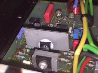
Hi , yes the voltages in post 2 are the main output transistors , I will check on the capacitor terminals after work .
That's a bit high for a 40Vac transformer.
Maybe they specified a special of around 230:42-0-42Vac and when running from a 245Vac UK supply gives that higher voltage.
Some manufacturers specify a maximum output power when the mains is at the nominal voltage. Others do that for the minimum mains supply voltage, with the result that at nominal supply voltages the amplifier gives a lot more power.
I recommend you find a good repair technician.
And where would be the fun in that !!,.. 😀
Most of the problems with this amp is the fact that the two transistors responsible for the voltage amplification is NOT fittet with a heatsink. As a result they run VERY HOT, and eventually break down. I can`t see the number, but one is a 2SA1209 and the other 2SC2911. Replace with 2SA1358/2SC3421, AND add heatsink.
regards
Roar
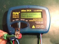
Good call , i took out the 2SC2911 transistors and sure enough their shorted between emitter and base

Last edited:
Hi Again , thought i would give an update on this ,. I replaced all 4 transistors with the ones RM suggested (thanks again for your help RM) and added diy heatsinks, the temperature these transistors are running at is around 51 degrees C , not sure what the acceptable temps are ?

I do have a bit of hiss through the rear speakers with the amp powered up (nothing being played ) im not sure that it wasnt there before though .
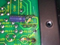
Whilst i had my IR thermometer out was checking some other temps and noticed the op amps had a difference of around 12 degrees C , i was reading up about upgrading the op amps but it looks like someone already has with OPA134PA (originals were TL071CP) on the back there is a cap between 2 of the pins and on the one which is running hotter has a resistor aswell ,(see pic) . The op amp input voltages are the same 24.1 v DC .

I dont know if this temperature difference is a problem or not or adding to the hiss , think i may renew the caps in the power supply section .
What do you guys reckon ?

I do have a bit of hiss through the rear speakers with the amp powered up (nothing being played ) im not sure that it wasnt there before though .
Whilst i had my IR thermometer out was checking some other temps and noticed the op amps had a difference of around 12 degrees C , i was reading up about upgrading the op amps but it looks like someone already has with OPA134PA (originals were TL071CP) on the back there is a cap between 2 of the pins and on the one which is running hotter has a resistor aswell ,(see pic) . The op amp input voltages are the same 24.1 v DC .

I dont know if this temperature difference is a problem or not or adding to the hiss , think i may renew the caps in the power supply section .
What do you guys reckon ?
Last edited:
I have been toying with the idea of getting an oscilloscope for a while now , would i be able to track down the component responsible for the hiss with one ?
Probably not.
But it is a good tool if you get deeper into diy.
The missus owes me a xmas pressie , ha ha , cant decide on a bench power supply or a scope ,,
Do you think the one op amp i have thats running hotter is any cause for concern ?
Both would be nice.
Try Ebay for secondhand working versions.
I bought my 3A+3A @ 0 to 30Vdc +5A @ 5Vdc for about £50
I have 20MHz & 100MHz dual channel scopes, both from Ebay.
I have a really old dual beam 10MHz scope that I bought locally way back before 1980. It's all valve/tube inside.
I built an accurate 0.1% resistance bank. Steps in 10r to 2M1, but the 1r0 steps from 0 to 9r0 has gone a bit variable due to poor switching. I need to buy a better switch.
I also built a switched T attenuator that does -0dB to -61dB in steps of 0.05dB
And a variety of DMM: bench (Ebay) and battery.
Both would be nice.
Try Ebay for secondhand working versions.
I bought my 3A+3A @ 0 to 30Vdc +5A @ 5Vdc for about £50
I have 20MHz & 100MHz dual channel scopes, both from Ebay.
I have a really old dual beam 10MHz scope that I bought locally way back before 1980. It's all valve/tube inside.
I built an accurate 0.1% resistance bank. Steps in 10r to 2M1, but the 1r0 steps from 0 to 9r0 has gone a bit variable due to poor switching. I need to buy a better switch.
I also built a switched T attenuator that does -0dB to -61dB in steps of 0.05dB
And a variety of DMM: bench (Ebay) and battery.
i went for this psu ,, TTi PL320 BENCH PSU 32V 2A with Digital LED Meters. Excellent Condition! | eBay
😀
I read with interest RM's comments for the repair of a Audiolab 8000P. With failed Q113,Q114 (Q213,214) The equivalents that were specified seem to have been discontinued by all of the reputable suppliers. 2SA1358 and 2SC3421. They can be found on eBay but most likely counterfeit and not to be trusted. Would there perhaps be an updated equivalent for these overheating transistors. The originals being 2SA1209S and 2SC2911S.
- Home
- Amplifiers
- Solid State
- audiolab 8000p has no output