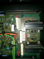
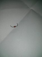
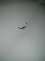
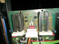
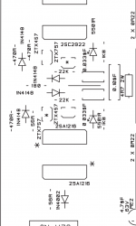
As the title suggests a coffee spill led to parts failure that I now wish to fix. Thinking of using Takman resistors for replacing the dodgy side and doing likewise on the other to match up both. The main problem is identification of a supposed diode, see pics attached, one of these diodes had blown and some resistors nearby had gave up the ghost. This is my first post and hope to be here for a long time picking up the soldering iron and modding and repairing hifi for the foreseeable future.
If anyone has schematics or a service manual for my particular amp it would be much appreciated. Cheers
If anyone has schematics or a service manual for my particular amp it would be much appreciated. Cheers
Attachments
There's a schematic available on HiFi Engine. https://www.hifiengine.com/manual_library/audiolab/8000p.shtml You need to register to download it but it's free and easy to join.
I suspect that more than a signal diode is damaged.
Start up the amp via a Mains Bulb Tester. The bulb will probably light up indicating a big over current.
Start up the amp via a Mains Bulb Tester. The bulb will probably light up indicating a big over current.
Thanks Andrew, I'm replacing all the resistors diodes and giving it a good clean round the affected area. What do you suggest after testing with a mains bulb tester Andrew?I found the diode I was looking for online. Cheers Jw for the schematics, but it's the later version of 8000p similar to the 8200p.
If the bulb lights up you will find that your supply rails will be just a few volts instead of ~40Vdc.
After each power OFF you need to discharge the PSU using a resistor. 2k2 will get hot. Don't burn your fingers.
The first step is to disconnect the amplifiers from the PSU. Now the bulb should be out. Check the PSU voltages. A resistor soldered to two crocodile clips with short insulated flexible leads is a handy tool.
Then connect ONLY the good channel amplifier and see if the bulb stays out.
If it does, can you safely measure voltages to see how they compare to the service sheet? Be careful a slipped probe can blow up the good channel.
Disconnect the good channel and connect the damaged channel.
The bulb will probably come on.
The next step is possibly to remove all the output transistors in the damaged channel. This will disconnect the feedback signal so output voltage will probably go to rail. If the bulb is still lit then you probably need to remove the driver transistors as well.
Last edited:
It's usually better to measure parts before just replacing blindly. It's quite easy to create new problems doing this. Definitely check transistors for shorts before applying power. You can still burn up parts with a bulb limiter in circuit. This can be done in circuit usually. Normally you can check voltage drop collector to base and emitter to base in diode check mode. Compare between the good and the bad channels.
Thanks Andrew and Jw for the info. I have a test lamp and meter so will check all these parts. The amp was still working on both channels ballanced, just the heatsink wasn't heating up on the spill side before I stripped the blown parts out.
Spillage is best removed by washing properly. I've dealt with dozens (into the hundreds) of such cases and the big problem is corrosion starting weeks/months/years down the line.
http://www.diyaudio.com/forums/car-audio/301813-washing-amplifier-board.html#post4942703
Those devices on the heatsink need to come off and have the mounting kits and hardware replaced imo.
http://www.diyaudio.com/forums/car-audio/301813-washing-amplifier-board.html#post4942703
Those devices on the heatsink need to come off and have the mounting kits and hardware replaced imo.
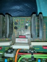
Thanks for all the info and I used contact cleaner and a small artist brush to get some of the residue off the board. It looks a bit better now, but don't like the idea of using soapy water though. Struggling to find this part or an equivalent DIODE BZV86-2V0 this is the part that spewed on the board after a dislike of coffee. Check the cleaned and partially stripped board.
Attachments
I think that's just a 2V zener. Did you find a schematic to match your amp?
The board still looks shiny like there's a goo residue. That goo might become conductive. A good wash with Isopropyl may help.
The board still looks shiny like there's a goo residue. That goo might become conductive. A good wash with Isopropyl may help.
Last edited:
Yes, repairs to liquid damaged equipment often fail in the future unless its all been cleaned properly.
Hot water and detergent is fine. Just pat it dry with paper towel to wick up most of the remaining water and then place on a warm to hot radiator for several hours.
Hot water and detergent is fine. Just pat it dry with paper towel to wick up most of the remaining water and then place on a warm to hot radiator for several hours.
warm/hot tap water and dish-washing detergent rubbed in/off with an old toothbrush works.
Shake off the water until nearly dry and then leave to dry out thoroughly before re-assembly.
Shake off the water until nearly dry and then leave to dry out thoroughly before re-assembly.
then place on a warm to hot radiator for several hours.
Following a recommendation that I've heard some time before, I decided to give it a try and put a very dirty (fat, dust, nicotine etc.) chassis of an old radio console into the dishwasher and have it dried in the warm sun for a few days. The unit became clean indeed, but I immediately observed a stuck potentiometer axis. And as I had to replace a tube socket, I became confronted with the fact that alcalic agents, such as dishwashers' detergents, successfully prevent from soldering. Not recommended anymore!
Best regards!
Best regards!
Following a recommendation that I've heard some time before, I decided to give it a try and put a very dirty (fat, dust, nicotine etc.) chassis of an old radio console into the dishwasher and have it dried in the warm sun for a few days. The unit became clean indeed, but I immediately observed a stuck potentiometer axis. And as I had to replace a tube socket, I became confronted with the fact that alcalic agents, such as dishwashers' detergents, successfully prevent from soldering. Not recommended anymore!
Best regards!
Usually the dishwasher method is done with no soap, top shelf and rinse cycle only. This is done with sealed pots only.
I have a Walter Bio Circle wash tank that does a great job, followed by water rinse, then distilled water rinse. I've also had excellent results with a Spray Nine product called Grez-off. https://www.spraynine.com/product/spray-nine-grez-off-heavy-duty-degreaser-5/ It's a mild alcohol based degreaser that will remove nicotine easily. Follow this with a thorough rinse in water, then distilled water.
The distilled water final rinse is important. Hard water deposits can be conductive.
Just finished replacing all the resistors from my previous pics including the 2V0 diode that was hard to find. Turned the amp on without speakers or source connected, turned off with no issues. Now have the amp sourced up, speakers connected, sounds great, but one heatsink is heating up more than the other (used thermal tape on the transistors to heatsink) it's not normal for one channel to heat up more than the other, but what may be causing this? Any help would be appreciated. Cheers
First thought would be that the bias is to high on the hot channel. That assumes that the DC offset is normal (near zero).
What was this replaced diodes function ?
What was this replaced diodes function ?
FEATURES
• Low-voltage stabilization
• Forward voltage range: 1.4 to 3.2 V
• Total power dissipation:
max. 330 mW
• Differential resistance range:
max. 20 to 35 Ω.
APPLICATIONS
• Power clipping
• Level shifting
• Low-voltage regulation
• Temperature stabilisation.
I still need to replace the same parts on the other side, just wanted to test first.
Diode is BZV86-2V0 it's what is stated in the service manual for that slot.
Thanks 🙂
I actually meant what does it do in the actual circuit. If its used as a voltage reference for setting a current (for example) then the replacement will almost certainly be a little different in terms of exact voltage. That could explain the bias being different, hence the heat.
I have an 8000 circuit but couldn't just see such a device on that one. Maybe the P version is different.
I'm just looking at the circuit in post #2 and I can't just spot it on there either.
What you need to do is measure the bias current of both channels for starters. That's easy to do by measuring the volt drop across either pair of the 0.22 ohm emitter resistors and calculating the current using ohms law.
What you need to do is measure the bias current of both channels for starters. That's easy to do by measuring the volt drop across either pair of the 0.22 ohm emitter resistors and calculating the current using ohms law.
- Status
- Not open for further replies.
- Home
- Amplifiers
- Solid State
- Audiolab 8000p and coffee