Hi all, this is my first post.
I have an Audiolab 8000A and want to install the "Preamp output muting" relay mod as described in a service manual that I found here: Login - HiFi Engine...
However, I've got a newer version, it has serial No. 207B91454 and has the CST207-018 Issue 8 board, PCB No. 41811.91. I think it's called the Mk3, one of the last versions built in the UK - black front with added video input. But I can't find it's schematics for it anywhere.
Ok, so the board has been redesigned, but the circuit still looks 98% similar to the old version. So I'm guessing that I can still do the mod I want, even though all the part numberings has been changed over time.
My questions:
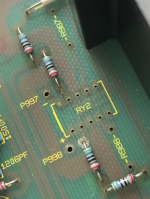
1. According to the old manual, I'm supposed to place a relay at RL2. But there is no RL2 on my circuit bord, but RY2 instead. Is RL2 and RY2 the same thing?
2. If RL2 is identical to RY2, can I still use the same 48V 2PCO 4000 ohm relay?
3. To power the relay coil the old manual says that "The two points marked RL2+ and RL2- (adjacent to relay RL2) must be wired to the corresponding points marked RL2+ and RL2- adjacent to the main relay RL1". However, there is no RL2+ nor RL2- on my board. But I suspect that P998 and P997 is the new names, and that the empty P995 and P996 are the points to get the power from. Am I right or wrong?
P.S. If someone could send me the schematics or service manual for my version, it would of course be awesome.
Thank you.
I have an Audiolab 8000A and want to install the "Preamp output muting" relay mod as described in a service manual that I found here: Login - HiFi Engine...
However, I've got a newer version, it has serial No. 207B91454 and has the CST207-018 Issue 8 board, PCB No. 41811.91. I think it's called the Mk3, one of the last versions built in the UK - black front with added video input. But I can't find it's schematics for it anywhere.
Ok, so the board has been redesigned, but the circuit still looks 98% similar to the old version. So I'm guessing that I can still do the mod I want, even though all the part numberings has been changed over time.
My questions:
1. According to the old manual, I'm supposed to place a relay at RL2. But there is no RL2 on my circuit bord, but RY2 instead. Is RL2 and RY2 the same thing?
2. If RL2 is identical to RY2, can I still use the same 48V 2PCO 4000 ohm relay?
3. To power the relay coil the old manual says that "The two points marked RL2+ and RL2- (adjacent to relay RL2) must be wired to the corresponding points marked RL2+ and RL2- adjacent to the main relay RL1". However, there is no RL2+ nor RL2- on my board. But I suspect that P998 and P997 is the new names, and that the empty P995 and P996 are the points to get the power from. Am I right or wrong?
P.S. If someone could send me the schematics or service manual for my version, it would of course be awesome.
Thank you.
Attachments

Hi, late reply, sorry. If you look at Separating the Pre and Power Sections on an Audiolab 8000A in the section on PCB issue 5, you'll see it refers to RL2/RY2, and it's in the position shown as RY2 on that PCB version - same place as the issue 8 PCB. (I have an issue 8 PCB myself and I'm just splitting the pre and power amps, and not sure whether to add pre-muting while I'm there).
Hi all,
there are a lot of topics on this amp, caps replacement etc, and so I decided to just post this here instead of opening another topic. Recently my Audiolab 8000a decided to act up a bit, left and right channel seemed to be off balance, ie: left side seemed to be softer than the right side. So i decided to recap the amp, starting from the PSU, till the tone/preamp circuit. at the same time, replace the plastic RCA jacks, and the Speaker posts as well, and i documented down what I know about this amp, the parts that i used and so on and so forth. I do realised that there are many other available variations available, so YMMV. feel free to use this information. Ref: audiolab 8000a service manual. can be obtained for free in hifiengine. Hopefully can serve as comprehensive guide to anyone who is working on this amp. Capacitor values are referenced off the Main PCB itself, and not from the Service manual. I'm not sure which iteration my amp is.
The Audiolab 8000A integrated amplifier
PCB board issue: CST207-018, Issue 8, Board SN: 42715.92
The Audiolab 8000A integrated amplifier circuit design
signal flow:
RCA input - selector switch - Balance control - Volume pot - preamp/tone control - preamp out/power amp
volume potentiometer:
Noble logarithmic, 30kohm, 28mm x 26mm x 30mm, Shaft 6mm, length 18mm, mounting diameter 8mm,
Replacement: ALPS Blue velvet, 50kohm, nearest size/fit
Balance potentiometer:
VR1, 1z250kohm x2 balance pot
components designation
The component, values and placement are all on the top silkscreen. Easily identifiable; and replaceable. Its coded as below, an alphabet, followed by 3 digit numbers
P - Power related/supply
C- capacitors
R- Resistors
Q- Transistors
D- Diodes
First Digit 1-8, 9
Odd number: left channel
Even number: right channel
1 - left channel for MC
2 - right channel for MC
3 - left channel for MM
4 - right channel for MM
5 - left channel for preamp
6 - right channel for preamp
7 - left channel for power amp
8 - right channel for power amp
9 - Power Supply unit
To separate Pre and Power Amp
Remove R980, R979 - this will disconnect the preamp stage to the power amp stage. this will isolate the preamp, as well as no inputs at all to the power amp, either from the preamp stage or via the power amp input RCA sockets.
however to be able to use the power amp as a stand alone, have to connect back a 560ohm to R985, R986 - does not correspond to the above naming/coding nomenclature. can leave it unconnected and the preamp section will function as it is. power amp will have ZERO input, none from the RCA jacks if R985,986 is not connected
Installing a DC blocking 1uf/160V polypropylene capacitor at the position of R985/R986 - PHE426MF7100JR06L2, size: 7.0(W) x16.5(H)x 26.0 (L), lead spacing 22.5mm
Doing so, will need the shorting of the preamp out into the power amp in - RCA center pin diameter 3.1mm, can use copper rod of 3mm
Preamp Out from preamp/tone control circuit to the RCA Jacks:
Via R526 for left channel, R626 for right channel
Line stage caps and values for single channel( obtained from the PCB)
C502/C602 - 4.7uf 50v
C501/C601 - 4.7uf 50v
C503/C603 - 220pf
C504/C604 - 680pf
C505/C605 - 10uf 35v
C506/C606 - 330n
C507/C607 - 220pf
C508/C608 - 47uf 35v
there are 2 polystyrene caps at the preamp stage - 22pf
Multiple EVOX MMK caps (grey? white?) - values as per printed on the PCB
EVOX PFR (blue color) - values as per printed on the PCB
All line stage electrolytics are changed to Elna Silmics II series in equivalent capacitance and upgraded voltage if size permits.
planning to change C507/C607 220pf caps to WIMA FKP2 series caps, polystyrene caps to Mica silver caps of equivalent values in the future.
Tone control
toward the front of the amp, same line/row as the vol, balance pot
multiple caps - not going to change anything here.
PSU caps (near the transformer)
C901 - 0.1uf 100v - using PHE426 series cap, online suggestions uses vishay MKP 1837
C935 - 0.01uf
C936 - 100uf 35v 5mm pitch
C937 - 100uf 35v 5mm pitch
C938 - 0.47
C939 - 100uf 35v 5mm pitch
Main power caps 10000uf, 50v x2
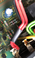
I think these are to power the power amp section. The tone control, preamp are powered by the smallish PSU/filter at the front left hand corner, bypassed a 41 DC voltage from the rectifier to the left side of the board, green and red wires running from the flat bridge rectifier. From the schematic diagram it is suppose to have a 30V DC output from the PSU at the left lower corner where the 2 regulator transistors are, 2SC3851 - digikey description: TRAN NPN 60V 4A TO-220F, and its paired 2SA1488 - digikey description PNP 80V 4A 15Mhz 25w through hole TO_220F. Measured with DMM Sanwa CD800a - 28VDC
Preamp/tone/MC/MM PSU
3 electrolytics, ELNA RE series
470uf 35v pitch 5mm
470uf 16v pitch 5mm x2
All power supplies electrolytics are swapped with nichicon UKL series
most electrolytics are 5mm pitch, except for main caps, which is solder lugs, mounted horizontally
D901 - rectifier diode: B80c5000A (80v5a) spec - flat bridge rectifier, company: ISKRA
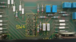
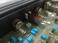
according the to service manual, can fit a relay at position RY2 to mute the preamp output during start up as well as after inserting a headphone jack. The appropriate relay to use is a panasonic TQ2-48V. HOWEVER, according to the manual, needs to be hot wired from main relay 1 for it to function. There are 2 points from nearby relay 1, P996, P995 (i think). VDC readout here is 24VDC, so am not sure whether to use TQ2-24, or TQ2-48. both from panasonic. direct fit. TQ2-12 is used in the Audiolab 8000DAC for output muting, size and output schematic is compared and found to be direct fit. ). UPDATE 29/4: no issues in the muting relay. TQ2-48 does works as it is suppose to, even with a 24V supply. Setbacks is there is an faint but audible pop in between CD tracks.
Shorted input
a direct shorted RCA plugs will eliminate RF or Cross talk in between input selectors and quietened down RF/noise/crosstalk
Speaker terminals:
To preserve the original look of the amp, chose to use Audionote AN-STR MEISHU, CON-030AG-10 as speaker terminals, chassis mounts, fully silver plated one-piece construction, non-magnetic, long thread for speaker crossovers, 10mm. This is due to the cut out speaker mounting plate measures 8mm across, same as the audionote speaker terminal. there are cheaper alternatives from Audio Note, most are direct replacement. Choice of this speaker terminal is to preserve the outlook as original as possible, terminal ends and solderable. planning to use solid core copper wiring, twisted pair and route it back onto the PCB. UPDATE 29/4: the speaker binding post mounts fit exactly the same as the original cutout of the chasis. no modificaton of the chasis needed
RCA jacks - dual, pitch 14mm x 14mm. - can get off ebay - choice chose - also to preserve original outlook.
Update 17/4/21: the insulator from the ebay jacks are painted on, it can be rubbed off with IPA. Option: Switchcraft 2x2 shielded RCA jacks, however need to modify the mounts as well as the grounding pin. UPDATE 29/4: the switch crafts are a bit shorter than the original RCA 14x14mm pitch 2x2 RCA jacks. the switchcraft can fit, but the grounding pin needs to be bent inwards and the mounting pin to be snipped of. that also will need an additional foam double sided tape for the correct mount height
C901 on the on the AC input from the transformer is 0.1uf 100Vdc, spacing 10mm. - use for filtering EMI/RFI? Ordered a few capacitors of same value and spacing, KEMET PHE426 series as well as a few others. will test this out. online suggetions to use Vishay MKP 1837 cap. UPDATE 29/4: installed KEMET PHE426 series cap.
unsoldered the op-amp TL071 IC and installed a 8 pin DIP socket. re-using the TL071 opamp for now. for easier upgrades in the future - OPA627, although meant for DC off set, but no harm trying.
Bias settings: the test pads are located underneath the PCB, needs to solder on wire terminals on for the bias to be checked and balanced. the 2 trim pots are meant for bias adjustments. prior to any adjustments, bias reading from both channels are 44mV +- 5-10mV. enough to make a difference? not sure. anyway for both sides i left it trimmed at about 44mV on each side. I just balanced both the channels for same reading, I did not trim it down to 22mV as per service manual setting as i find that it is running quite well prior to messing with the bias.
there are a lot of topics on this amp, caps replacement etc, and so I decided to just post this here instead of opening another topic. Recently my Audiolab 8000a decided to act up a bit, left and right channel seemed to be off balance, ie: left side seemed to be softer than the right side. So i decided to recap the amp, starting from the PSU, till the tone/preamp circuit. at the same time, replace the plastic RCA jacks, and the Speaker posts as well, and i documented down what I know about this amp, the parts that i used and so on and so forth. I do realised that there are many other available variations available, so YMMV. feel free to use this information. Ref: audiolab 8000a service manual. can be obtained for free in hifiengine. Hopefully can serve as comprehensive guide to anyone who is working on this amp. Capacitor values are referenced off the Main PCB itself, and not from the Service manual. I'm not sure which iteration my amp is.
The Audiolab 8000A integrated amplifier
PCB board issue: CST207-018, Issue 8, Board SN: 42715.92
The Audiolab 8000A integrated amplifier circuit design
signal flow:
RCA input - selector switch - Balance control - Volume pot - preamp/tone control - preamp out/power amp
volume potentiometer:
Noble logarithmic, 30kohm, 28mm x 26mm x 30mm, Shaft 6mm, length 18mm, mounting diameter 8mm,
Replacement: ALPS Blue velvet, 50kohm, nearest size/fit
Balance potentiometer:
VR1, 1z250kohm x2 balance pot
components designation
The component, values and placement are all on the top silkscreen. Easily identifiable; and replaceable. Its coded as below, an alphabet, followed by 3 digit numbers
P - Power related/supply
C- capacitors
R- Resistors
Q- Transistors
D- Diodes
First Digit 1-8, 9
Odd number: left channel
Even number: right channel
1 - left channel for MC
2 - right channel for MC
3 - left channel for MM
4 - right channel for MM
5 - left channel for preamp
6 - right channel for preamp
7 - left channel for power amp
8 - right channel for power amp
9 - Power Supply unit
To separate Pre and Power Amp
Remove R980, R979 - this will disconnect the preamp stage to the power amp stage. this will isolate the preamp, as well as no inputs at all to the power amp, either from the preamp stage or via the power amp input RCA sockets.
however to be able to use the power amp as a stand alone, have to connect back a 560ohm to R985, R986 - does not correspond to the above naming/coding nomenclature. can leave it unconnected and the preamp section will function as it is. power amp will have ZERO input, none from the RCA jacks if R985,986 is not connected
Installing a DC blocking 1uf/160V polypropylene capacitor at the position of R985/R986 - PHE426MF7100JR06L2, size: 7.0(W) x16.5(H)x 26.0 (L), lead spacing 22.5mm
Doing so, will need the shorting of the preamp out into the power amp in - RCA center pin diameter 3.1mm, can use copper rod of 3mm
Preamp Out from preamp/tone control circuit to the RCA Jacks:
Via R526 for left channel, R626 for right channel
Line stage caps and values for single channel( obtained from the PCB)
C502/C602 - 4.7uf 50v
C501/C601 - 4.7uf 50v
C503/C603 - 220pf
C504/C604 - 680pf
C505/C605 - 10uf 35v
C506/C606 - 330n
C507/C607 - 220pf
C508/C608 - 47uf 35v
there are 2 polystyrene caps at the preamp stage - 22pf
Multiple EVOX MMK caps (grey? white?) - values as per printed on the PCB
EVOX PFR (blue color) - values as per printed on the PCB
All line stage electrolytics are changed to Elna Silmics II series in equivalent capacitance and upgraded voltage if size permits.
planning to change C507/C607 220pf caps to WIMA FKP2 series caps, polystyrene caps to Mica silver caps of equivalent values in the future.
Tone control
toward the front of the amp, same line/row as the vol, balance pot
multiple caps - not going to change anything here.
PSU caps (near the transformer)
C901 - 0.1uf 100v - using PHE426 series cap, online suggestions uses vishay MKP 1837
C935 - 0.01uf
C936 - 100uf 35v 5mm pitch
C937 - 100uf 35v 5mm pitch
C938 - 0.47
C939 - 100uf 35v 5mm pitch
Main power caps 10000uf, 50v x2
I think these are to power the power amp section. The tone control, preamp are powered by the smallish PSU/filter at the front left hand corner, bypassed a 41 DC voltage from the rectifier to the left side of the board, green and red wires running from the flat bridge rectifier. From the schematic diagram it is suppose to have a 30V DC output from the PSU at the left lower corner where the 2 regulator transistors are, 2SC3851 - digikey description: TRAN NPN 60V 4A TO-220F, and its paired 2SA1488 - digikey description PNP 80V 4A 15Mhz 25w through hole TO_220F. Measured with DMM Sanwa CD800a - 28VDC
Preamp/tone/MC/MM PSU
3 electrolytics, ELNA RE series
470uf 35v pitch 5mm
470uf 16v pitch 5mm x2
All power supplies electrolytics are swapped with nichicon UKL series
most electrolytics are 5mm pitch, except for main caps, which is solder lugs, mounted horizontally
D901 - rectifier diode: B80c5000A (80v5a) spec - flat bridge rectifier, company: ISKRA
according the to service manual, can fit a relay at position RY2 to mute the preamp output during start up as well as after inserting a headphone jack. The appropriate relay to use is a panasonic TQ2-48V. HOWEVER, according to the manual, needs to be hot wired from main relay 1 for it to function. There are 2 points from nearby relay 1, P996, P995 (i think). VDC readout here is 24VDC, so am not sure whether to use TQ2-24, or TQ2-48. both from panasonic. direct fit. TQ2-12 is used in the Audiolab 8000DAC for output muting, size and output schematic is compared and found to be direct fit. ). UPDATE 29/4: no issues in the muting relay. TQ2-48 does works as it is suppose to, even with a 24V supply. Setbacks is there is an faint but audible pop in between CD tracks.
Shorted input
a direct shorted RCA plugs will eliminate RF or Cross talk in between input selectors and quietened down RF/noise/crosstalk
Speaker terminals:
To preserve the original look of the amp, chose to use Audionote AN-STR MEISHU, CON-030AG-10 as speaker terminals, chassis mounts, fully silver plated one-piece construction, non-magnetic, long thread for speaker crossovers, 10mm. This is due to the cut out speaker mounting plate measures 8mm across, same as the audionote speaker terminal. there are cheaper alternatives from Audio Note, most are direct replacement. Choice of this speaker terminal is to preserve the outlook as original as possible, terminal ends and solderable. planning to use solid core copper wiring, twisted pair and route it back onto the PCB. UPDATE 29/4: the speaker binding post mounts fit exactly the same as the original cutout of the chasis. no modificaton of the chasis needed
RCA jacks - dual, pitch 14mm x 14mm. - can get off ebay - choice chose - also to preserve original outlook.
Update 17/4/21: the insulator from the ebay jacks are painted on, it can be rubbed off with IPA. Option: Switchcraft 2x2 shielded RCA jacks, however need to modify the mounts as well as the grounding pin. UPDATE 29/4: the switch crafts are a bit shorter than the original RCA 14x14mm pitch 2x2 RCA jacks. the switchcraft can fit, but the grounding pin needs to be bent inwards and the mounting pin to be snipped of. that also will need an additional foam double sided tape for the correct mount height
C901 on the on the AC input from the transformer is 0.1uf 100Vdc, spacing 10mm. - use for filtering EMI/RFI? Ordered a few capacitors of same value and spacing, KEMET PHE426 series as well as a few others. will test this out. online suggetions to use Vishay MKP 1837 cap. UPDATE 29/4: installed KEMET PHE426 series cap.
unsoldered the op-amp TL071 IC and installed a 8 pin DIP socket. re-using the TL071 opamp for now. for easier upgrades in the future - OPA627, although meant for DC off set, but no harm trying.
Bias settings: the test pads are located underneath the PCB, needs to solder on wire terminals on for the bias to be checked and balanced. the 2 trim pots are meant for bias adjustments. prior to any adjustments, bias reading from both channels are 44mV +- 5-10mV. enough to make a difference? not sure. anyway for both sides i left it trimmed at about 44mV on each side. I just balanced both the channels for same reading, I did not trim it down to 22mV as per service manual setting as i find that it is running quite well prior to messing with the bias.
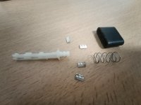
Hi brother , my audiolab 8000A ,the tone button broken down, I removed it out , now need you help to advice me , which point to point need to solder together ,so can have the sound back again.. thanks for the helps ,I do mark a number on the picture , which one should I solder together? Thanks.. urgent.Superb pre-amps, but horrible power-amp;-)-;
And: De-solder and re-solder.-)
Attachments
- Home
- Amplifiers
- Solid State
- Audiolab 8000A - preamp mod and schematics question