ok here is a few facts and a few questions around the audiolab 8000 a
---First to notice that units in production till 1992 are equipped with 220V trafos so many of these units with now days 230-240 voltage in Europe will produce almost 43 +43 volts after the capacitors and these few 3-5 volts more per rail will eventually stress the amp and coloration of burned pcb will be there
---Also noticed that either after year 1992 trafos are different so with 230Ac produce almost 40 Volt ( or they simply realized that they are stressing the wrong circuit with the wrong ways.)
---the audio lab 8000S is an sziklai or CFP if you like that means that the double VBE multiplier lays on the drivers .
---Let us forget for a minute the weird bias procedure where a tech is requested to remove covers install probes re install covers and adjust the bias 😱😱😱
---Real problem is that the ventilation designed works only for the outputs and the rest of the amp is tight sealed where in the driver area temperature will increase then the Vbe multiplier will drop the bias according to the temperature ....probably over compensate and reduce the bias more than needed .
so Solution 1 will be to almost over bias the amplifier and expect the VBE multiplier to finally adjust something more reasonable when the pcb are will reach the ""operating'' temperature
Drawbacks will be
--that you still going to stress the pcb and parts around the amp
--will take quite a lot of time for the amp to stabilize a temperature
--And don't know why but i still think that there is still going to be some thermal run away
or Solution 2 drill fins or long ventilation halls above the driver area
---Bias the amp to the manual stated bias
---Defuse all the concentrated heat from inside the box
---Allow the Vbe multiplier to adjust the bias only when amp is stressed
i dont see any drawback here ....
opinions please
kind regards
sakis
Last edited:

let me not forget how many in a way arrogant designers produced equipment in England and simply missed that one of their amplifier may find its way to a Mediterranean or any other 10 degrees warmer country .
Lets make that 15 C warmer. When I was in Andalucia a couple of weeks ago, temps were hitting 30-35 C there while here temps were struggling to reach 16-18 C...
Last edited:
I was actually expecting more people to jump in with comments on this ....
I am willing to drill the cover anyway and monitor bias for 24 hours in various playing conditions to see how it will go
I may as well do that before and after drilling
Good thing for my testing is that as we speak in Athens we have max temp. of 34 degrees ( having a blast with a second summer my kids are on the way to spent another day on the beach !!! )
kind regards
sakis
Hi Sakis, how are you at 34 degrees? I know about using northern European amplifiers in warm climates too! 
If the driver stage is the one being thermally compensated, why is there a problem if it gets particularly hot? The Vbe multiplier or diodes should continue to provide fairly linear bias control according to the driver case temperature, whatever it is within reason - if it is in thermal contact. The temperature sensed does not have to track the output stage temperature at all, AFAIK, so this should not affect the bias control.
If you are just trying to reduce driver temperature by ventilation, it should continue to work but perhaps the response curve of the Vbe compensation voltage may not be in the same linear or flat region any more. I would think, as you suspect, that tweaking the bias level to produce lower bias and driver dissipation will result in undercompensation, perhaps runaway but ideally it should track according to Douglas Self''s figuring and graphs in his chapter on "Thermal compensation and thermal dynamics". It's in each edition and not hard to find, even on the web, in defiance of copyright.
Optimally biased CFP stages run cold at typical domestic power output - cold like the sound quality. Then there are several designs with high bias of 70-100 mA, like old Hitachi designs and, of course, the DIY P3a. The high bias designs really complicate thermal compensation because they vary so much from ambient temperature differences and warm-up yet very little from the power output, until you turn up the power and this is reversed. These are a real hassle, so anyone who builds a technically correct comp. circuit for this deserves a medal, IMO. The air-spaced type, as used in the P3a, seems much easier to apply.
Hello Ian ( always nice to see you around my quests ) !!!
I will post a copy of the ""bias adjustment procedure "" according to the service manual which if i manage to understand the two (??? ) (!!!) pages correctly the approach of the designer is as i said
Over bias the amplifier at the bench while tuning ...close the cover allow the amp to built the temperature inside the case and expect the VBE to take it down to a reasonable level after warming up .
Imagine what will happen if the procedure is to take place with ambient temp of 22 degrees and add another 15 or more the amplifiers operating temperature inside the case
we are talking something like 65-70 degrees on the driver heatsink ...that is way too much
I am setting up as we speak a measuring set up for both temperature and bias so in a few days i will have proper graphs of how bias and temperature rising in various operating modes idle - casual listening - average power
Kind regards
Sakis
70 degrees? Wow! Just to be clear, is the Vbe multiplier attached to the driver(s), not with an air gap. Is that correct?
The procedure you describe sounds like there is no thermal connection there, so it has to be sealed and adjusted carefully to make the setup conditions like the operating conditions. That's awkward, like it sounds and crazy too.
I would still go with your plan to allow air flow or, if possible, increase heatsinking to reduce mean ambient temperatue around the drivers. Perhaps the only problem then is the possibility of hole blockage with dust or trying to use the amp in a bad position etc.
I look forward to your test results anyway. Good luck
yeap that is correct
In this audiolab the VBE is double and also perfectly attached one of them to each driver ...that will make over compensation far more easy
In this audiolab the VBE is double and also perfectly attached one of them to each driver ...that will make over compensation far more easy
*bump*
In the only manual I can find (207 Serial nos 87 89) it states that the voltage across the emitter resistor should be 22mV for a quiescent current of 50mA. The circuit has these resistors as 0.22 ohm. So anyone setting it up with 22mV gets a bias current of 100mA.
Is this an error in the manual? I wonder how many of these amps are running hot for this reason.
*bump*
In the only manual I can find (207 Serial nos 87 89) it states that the voltage across the emitter resistor should be 22mV for a quiescent current of 50mA. The circuit has these resistors as 0.22 ohm. So anyone setting it up with 22mV gets a bias current of 100mA.
Is this an error in the manual? I wonder how many of these amps are running hot for this reason.
Do the instructions tell you to measure across a single emitter resistor of across a pair? Measuring across a negative and a positive rail emitter resistor would be 0.44 ohms which would work out to 50mA.
Aha! Of course. Thanks. I'm going to break in to the circuit and measure it direct. There is no thermal feedback as far as I can see, which always worries me. They do run quite hot which also worries me. The one I'm working on has presets, not shown in that circuit. I don't like to see them doing this job unless they're on the base emitter side. Nothing else bears much relationship to the diagram either, all the numberings start with 7,8 or 9.
Voltage across one emitter resistor is 25mV and 44mV on the other (across one resistor). This is bad news. Someone's been twiddling, another good reason not to have presets.
I do like these amps though, lovely sound into these Celestion SL6S.
Another question; I'd like to include a voltage drop resistor in the supply to the 30V regulator circuit, just to take the heat off those poor little transistors. Any reason why this would be a problem? Here's the circuit-
An externally hosted image should be here but it was not working when we last tested it.
Last edited:
I measured the current going to the 30v regulator and its nearly 300mA, so it's dissipating about 4 watts. No wonder it gets hot. Adding a 22 ohm resistor in series will take some of the load off it, clamped to the side of the case. It should probably have a cap to ground after it too.
Hi, Sakis,
My audiolab 8000A is a 1988 model. It has labelled 220V at rear. Looking at the service manual, the voltage across the big supply capacitor is normally +44 V and –44 V assuming the mains voltage at home is absolutelly the same as the labelled voltage at the amplifier rear.
So for that models and versions, the "normal" is +44 V and –44V. However, in my country (Portugal) the mains voltage is now 230 V nominal, but can vary ( by formal specification) between –11% and +6% of the nominal value.
As my amplifier is labelled 220 V, using 230 V gives +45,7 V and –45,9 V at the supply capacitors. I can have, sometimes, rarelly, 243V. We know the supply filter capacitors (10000 uF) are rated for 50 V, too close, and the whole amplifier is designed for no more than ±44 V supply...
I know it is overload, but there is very little that I can do. The transformer do not has several taps for adapting to different voltages. So there are only 2 options: 1. Change/replace the transfomer; 2. Put a big transformer 230 V to 220 V (>300W) before the amplifier. None of them is practical...
Guilherme.
You could install some power ripple eaters in the B+/B- rails to drop a volt or so. Or even low dropout voltage regulators.
You can add an external transformer wired as an auto-transformer to drop a few volts, say 12V . The added transformer has modest size, since its secondary has to carry only the curent drawn by the Autiolab. You house the transformer in outboard enclosure with a receptacle for your amp’s power plug.
This sort of adapter is done elsewhere in the forum. Please advise if it’s not clear.
This sort of adapter is done elsewhere in the forum. Please advise if it’s not clear.
Thnks. Such transformers are not a available currently. I corrected the bias current which was higher than recommended and the amplifier runned too hot. I will describe this in my following post.
I ajusted recently the bias current on my Audiolab 8000A (version of 1988, issue 3).
May be my particular personal experience doing this can be useful to someone. The amplifier runned very hot. So I'm sharing this experience, so the following is my particular personal experience.
This version has not presets and bias current is set by the pair of SOT resistors R809//R811 on L channel, and R810//R812 on R channel. In each channel, the pairs of resistors are connected in paralel (//). In my amplifier, R809 was 6k8 and R811 was 43k. Also, R810 was 6k8 and R812 was 43k.
Please note the pairs above are also in parallel with another resistor (placed on component side) of 1k5 , labelled as R807 on L channel and R 808 on channel R. Then (considering the 1k5 resistor) changes on the 43k resistor have very very small effect in the bias current. After some tests, performed as stated in the service manual, I set at 7k5 for R809 (L) and 7k15 for R810 (R), both preferred values, the first on E24 series and the second on E48 series). The 43k resistors were not changed.
SOT resistors were selected with the amplifier cover and baseplate mounted, but without screws fitted (as specified on the service manual). There is (by construction) a "heat chamber" inside the amplifier and this temperature rise inside controls the bias current in such a way it reduces slowly the bias, taking about 30 minutes to stabilize. As a curious test, taking the cover off the "heat chamber" lowers its temperature and the bias increases (ambient temperature was 26 ⁰C). So, a bias setting with cover off is not valid. And gives place to a too low bias when the amplifier is working with its cover in place.
As stated on the service manual, the bias current is obtained by measuring (at each chanell) the voltage across each double emitter resistor (2×0.22ohm). Using Ohm's law, dividing the measured voltage by 0.44 we obtain the bias current. The manufacturer specified value is 50mA±20%, so the voltage across 0.44ohm will be 22mV±20%.
The Audiolab 8000A is prone to bias drift with time to higher values. And so the amplifier overheats even playing at low volume sound.
The Audiolab 8000A is prone to bias drift with time to higher values. And so the amplifier overheats even playing at low volume sound.
My experience: There will be no problems, even if your 50 volt electrolytic capacitors will occasionally see 55 volts.
Its heat sinks are quite small for what it is supposed to be able to do on paper. I would adjust the bias according to the transformer and heat sink. This circuit sounds coarse, gray, flat, torn anyway. A lower bias doesn't make much difference.
Its heat sinks are quite small for what it is supposed to be able to do on paper. I would adjust the bias according to the transformer and heat sink. This circuit sounds coarse, gray, flat, torn anyway. A lower bias doesn't make much difference.
Thanks, Cumbb,
As I specified above, I already adjusted the bias for about 20 mV across emitter resistors (=45 mA). Sounds OK. The amplifier runned too hot, now is more on the warm side.
On the power supply capacitors there is now 44,7 V/45,5 V, when mains is at 234 V. Offset is at 2,7 mV at one channel and 8,1 mV on the other, and this seems OK.
Tone controls are IMHO a usefull feature. I rarelly us them, but not all recordings are tonally equilibrated, and in some recordings they are usefull. And in 'purist mode' we can cancel them with a direct flat button. But many manufacturers, including Audiolab in recent years are prone the 'convince us' that such controls are evil... Even when we do not use them, it is good to know they are there, just on cause...
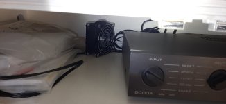
I also put a 92 mm fan, just in cause (attached image), to use if necessary...
As I specified above, I already adjusted the bias for about 20 mV across emitter resistors (=45 mA). Sounds OK. The amplifier runned too hot, now is more on the warm side.
On the power supply capacitors there is now 44,7 V/45,5 V, when mains is at 234 V. Offset is at 2,7 mV at one channel and 8,1 mV on the other, and this seems OK.
Tone controls are IMHO a usefull feature. I rarelly us them, but not all recordings are tonally equilibrated, and in some recordings they are usefull. And in 'purist mode' we can cancel them with a direct flat button. But many manufacturers, including Audiolab in recent years are prone the 'convince us' that such controls are evil... Even when we do not use them, it is good to know they are there, just on cause...
I also put a 92 mm fan, just in cause (attached image), to use if necessary...
Attachments
- Home
- Amplifiers
- Solid State
- Audiolab 8000 A bias issues