I have 20v on the right channel , this is after replaceing the output and driver transistors. I checked all resistors on this side also.
Am I missing something?
Am I missing something?
do you mean the voltage going from the drivers to the output?
all three legs of the drivers have between 17 to 20 volts
all three legs of the drivers have between 17 to 20 volts
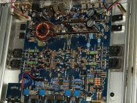
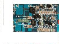
The driver (2sd600) and a pre-driver (2sa1023) were also defective. There was also an open 47 ohm resistor (next to R63E in the photos)
that was from repair notes from a 6601t on the dvd
I am beginning to think that is my problem
that was from repair notes from a 6601t on the dvd
I am beginning to think that is my problem
Perry knows much more than I, but if I had that kind of power on the bases I would find where it is coming from to start with. It should be the same layout as the other side.
If you have +20v on the speaker terminal (black meter probe on the secondary center tap of the power transformer and red probe on the 3rd leg of the output transistors of the defective channel), either the NPN transistor is leaking (electrically - not likely since it's new) or it's being driven on by another component. Measure the DC voltage from leg 1 to leg 3 of the NPN output transistor. What is the voltage from 1-3 (black probe on 3)?
What is the voltage from 1-3 on the PNP output (red probe on leg 3)?
What is the voltage from 1-3 on the PNP output (red probe on leg 3)?
If that's the case, it appears that you have no negative rail voltage. Look for broken connections on the wire jumpers leading from the rectifiers to the center leg of the PNP output transistor.
Also confirm that you have less than 1 ohm between leg 3 of the NPN output transistor and leg 3 of the PNP output transistor.
If there is a defective driver or other component, the amp may draw significant current when the connection to the rails is restored. Have the transistors tightly clamped to the sink when you power it up.
I have zero ohms between both transistors
I still have found no broken connections between the rectifiers and center leg of the pnp
the other channel works fine after replacing outputs.
I still have found no broken connections between the rectifiers and center leg of the pnp
the other channel works fine after replacing outputs.
With the amp off, measure the resistance between the center legs of the NPN output transistors on opposite sides of the amp. You should read ~0 ohms.
Do the same for the PNP outputs. You should read 0 ohms between the center legs but it's likely that you won't. If you don't read ~0 ohms, there is an open connection.
Do the same for the PNP outputs. You should read 0 ohms between the center legs but it's likely that you won't. If you don't read ~0 ohms, there is an open connection.
I read the voltage wrong. You had a leading 0 on the number and I took it as 0.39.
The following schematic should be similar to yours. You'll have to work out which component is which but it should be simple enough on this amp using an ohm meter.
You can right-click to zoom in on the file.
http://www.bcae1.com/temp/unknownaudiobahn01.swf
Print this out and label the transistors with the designations on your board so it will be less confusing. If you don't know how to read a schematic, compare the voltages on the transistors that are connected together to see where the voltages vary significantly and post your findings.
- Status
- Not open for further replies.
- Home
- General Interest
- Car Audio
- audiobahn a2201t