Hi,
I'm trying to rebuild an organmate reverb unit. What I don't know is what type of audio transformer is used here. In the schematic i see d.c. resistanctes of the audio transformer and the reverb spring. But I guess that does not help so much. Can you help me? 😕
Schematic: https://www.tonewheel.com/Schematics/Organmate.pdf
Nothing happened to it. I just want to build a second unit based on the original one. The audio transformer is the only part that confuses me. There are so many audio transformers with different values. I heard that the output impedance of the tube is very high and the input impedance of the reverb spring is very low....but i do not have absolute values.
Do you have a match for the reverb tank? They come in a dozen different impedances.
The transformer secondary should be nominally "same as" the tank input impedance.
The tube impedance is not too fussy. 1k, 5k, in there. BUT you want to match what you have. It would be best to measure the existing transformer. Good lesson in electricity.
The transformer secondary should be nominally "same as" the tank input impedance.
The tube impedance is not too fussy. 1k, 5k, in there. BUT you want to match what you have. It would be best to measure the existing transformer. Good lesson in electricity.
Send original one to a rewinder and ask for a duplicate or two.
Or forget the weird Organmate and build a Fender type reverb instead, for which you can buy ready made transformers off the shelf.
Transformer - Fender(R) Replacement, Output, 3-1/2 W, 8 Ohm | Antique Electronic Supply
Transformer - Fender(R) Replacement, Output, 3-1/2 W, 8 Ohm | Amplified Parts
Or forget the weird Organmate and build a Fender type reverb instead, for which you can buy ready made transformers off the shelf.
Transformer - Fender(R) Replacement, Output, 3-1/2 W, 8 Ohm | Antique Electronic Supply
Transformer - Fender(R) Replacement, Output, 3-1/2 W, 8 Ohm | Amplified Parts
Just compare it to most other Reverb circuits.
More important, others are "doable", this one relies on a non existing unknownn parameters transformer.
Unless, as I suggested earlier, you reverse engineer the original one.
In fact there is an SS solution from 1968 which has the same architecture (gain stage > follower > high impedance tank > recovery preamp > mixer) but I won´t even suggest it because many hate silicon ,so .......
In fact there is an SS solution from 1968 which has the same architecture (gain stage > follower > high impedance tank > recovery preamp > mixer) but I won´t even suggest it because many hate silicon ,so .......
I wanted to build a reverb using a Class D amp to drive it and possibly FET recovery but I have been hesitant as my tanks were higher impedance. Then I finally decided to check the resistance of the spring 'tank' (no actual 'chassis') from a Yamaha organ I just picked up for $20. The tank had roughly 4 ohms resistance, should do nicely on 12V or about there.
Why tinker with a class D driver amplifier, as the power demand of spring reverb tanks is well below 1 watt? And remember that the driver amplifier shold be of high output impedance, ideally an AC CCS, for good results.
Best regards!
Best regards!
As far as I know, the OrganMate uses a Gibbs Type 4 Reverb tank. I have two of these tanks myself (Philips used them in some of their top-of-the-line tube radios). Years ago, after some digging on the internet, I noted down that the input impedance of this tank is 1475 Ohm and the output impedance is 2575 Ohm. I measured the dc-resistance being about 180 Ohm for both the input and output coil in one tank.
A link to a discussion in which one of the contributors wrote (see post #4) that he measured the primary impedance of the driver transformer (part number: TMI DT-104) of a OrganMate being 7K at 1kHz, using a 1K5 resistor at the secondary tot mimic the tank: Tube reverb driver circuits - Music Electronics Forum
His result would mean the driver transformer has a turns ratio of about 2.2 to 1.
Last edited:
Why tinker with a class D driver amplifier, as the power demand of spring reverb tanks is well below 1 watt? And remember that the driver amplifier shold be of high output impedance, ideally an AC CCS, for good results.
Best regards!
Cheap and ready made, just buffer the input. Just curious, will do its own thread if it goes anywhere.
I suggest you check what 80% of manufacturers use (such as Fender/Laney/Marshall/Peavey) to get reverb in their amplifiers.
Most basic is just a TL072, go figure.
One half driving the high impedance tank constant current, which makes it happy, the other recovering delayed signal.
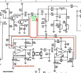
Here´s the Peavey example:
Most basic is just a TL072, go figure.
One half driving the high impedance tank constant current, which makes it happy, the other recovering delayed signal.
Here´s the Peavey example:
Attachments
Didn't think the TL072 could put out the current needed to drive a four ohm tank. Good to know. Oh wait, high impedance tank. I was trying to do a low impedance tank.
Last edited:
We are talking the Organmate reverb tank here, and it´s high impedance.
Again, in principle thread answers are for the original poster.
Again, in principle thread answers are for the original poster.
...I was trying to do a low impedance tank.
LM386 and a few dozen ohm resistor.
We are talking the Organmate reverb tank here, and it´s high impedance.
Again, in principle thread answers are for the original poster.
I wasn't sure if you were answering me or the OP. Thought he wanted to use the original circuit so I answered.
LM386 and a few dozen ohm resistor.
Reply button does not seem to work for me. Yes, thought about using one, have a few. Didn't really want to spend too much time in this thread about it. Basically I wanted to show there are many ways to skin a cat. Hoping to do a thread on it soon.
...Reply button does not seem to work for me.....
Replying/Quoting problems
{hack: hit "+" then "Reply". The + marks that last message for quoting. Do NOT let the moderators find you over-quoting.}
- Home
- Live Sound
- Instruments and Amps
- Audio Transformer for OrganMate