Hi guys,
Is anybody familiar with these type of amplifiers?
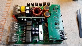
This amplifier died in my own car 2 years ago.
First this amp draw excessive current on the TDF8591TH modules, so I replaced it. They got killed again and doesn't create a PWM output.
The amplifier has a DC voltage on the speaker terminals again (draws no excessive current luckely, so I can troubleshoot)
Nothing really seemed burned.
Some TDF8591TH measurements.
Pin 6 measures 5V on both modules
Pin 7 got the pwm oscillation on both modules
Pin 1 and 12 measures -23v on both modules
Pin 3 and 10 doesn't measure a decent positive supply voltage on both modules (shouldn't this be +23v on both modules?)
Pin 14 reads 23v on both modules
Pin 23 reads 23v on both modules
Pin 16 and Pin 21 has no output PWM
Anybody got any idea?
Is anybody familiar with these type of amplifiers?
This amplifier died in my own car 2 years ago.
First this amp draw excessive current on the TDF8591TH modules, so I replaced it. They got killed again and doesn't create a PWM output.
The amplifier has a DC voltage on the speaker terminals again (draws no excessive current luckely, so I can troubleshoot)
Nothing really seemed burned.
Some TDF8591TH measurements.
Pin 6 measures 5V on both modules
Pin 7 got the pwm oscillation on both modules
Pin 1 and 12 measures -23v on both modules
Pin 3 and 10 doesn't measure a decent positive supply voltage on both modules (shouldn't this be +23v on both modules?)
Pin 14 reads 23v on both modules
Pin 23 reads 23v on both modules
Pin 16 and Pin 21 has no output PWM
Anybody got any idea?
Attachments
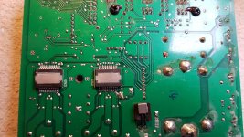
The datasheet shows a 10 ohm resistor in series with 3 and 10. It may be open if the amp uses the reference design. Page 19.
https://www.mouser.com/datasheet/2/302/TDF8591TH-600199.pdf
https://www.mouser.com/datasheet/2/302/TDF8591TH-600199.pdf
Correct, multimeter reads 0ohm between Pin3 and Pin10.
Do you think there is supposed to be +23v on Pin3 and Pin10?
On the other side of the PCB the resistors seems ok. No strange readings.
Do you think there is supposed to be +23v on Pin3 and Pin10?
On the other side of the PCB the resistors seems ok. No strange readings.
I didn't spend a lot of time with the datasheet but that's what it looked like to me.
Read between the corresponding low-side points to see if you read a 10 ohm resistor.
Read between the corresponding low-side points to see if you read a 10 ohm resistor.
You were right. 10ohm resistors which were high out of tolerance.
Positive +23v was present again, and one module created an output PWM again. Other module still had DC voltage on the terminals. Replaced the TDF8591TH and all 4 channels worked properly again.
Thanks Perry 😀
Positive +23v was present again, and one module created an output PWM again. Other module still had DC voltage on the terminals. Replaced the TDF8591TH and all 4 channels worked properly again.
Thanks Perry 😀