In case of any serious fault (or just in case of a successful startup), you can activate a two-transistor latch to short the zener reference to ground, forcing the user to unplug the circuit from mains, wait several minutes and apply power again in order for the circuit to restart (time would depend on how much the mains filter capacitors take to discharge).
Also, employing an under-voltage lockout feature like the one I proposed allows for automatic periodic restart without dissipation issues. If you trigger a latch shutting down the control IC, the auxiliary winding would no longer provide more power, so the voltage at the 100uF capacitor would decrease until UVLO is activated. Then, after the load is disconnected, it would start charging again until 24V are reached and a new startup attempt would begin...
Also, employing an under-voltage lockout feature like the one I proposed allows for automatic periodic restart without dissipation issues. If you trigger a latch shutting down the control IC, the auxiliary winding would no longer provide more power, so the voltage at the 100uF capacitor would decrease until UVLO is activated. Then, after the load is disconnected, it would start charging again until 24V are reached and a new startup attempt would begin...
Thanks for the additional info, Eva.
Channel-N. Tomorrow I look for the schematics of the simulation that I did for the capacitor-coupled base, and the waveforms resulting, and post them here.
Best regards,
Pierre
Channel-N. Tomorrow I look for the schematics of the simulation that I did for the capacitor-coupled base, and the waveforms resulting, and post them here.
Best regards,
Pierre
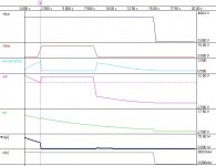
Here is the simulation, as promised.
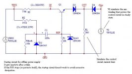
As you can see, it is quite similar to the classical NPN startup circuit. But the reference is AC coupled with a 220uF capacitor (C1).
Initially, C1 is discharged, so the voltage at "a" is the D2 zener voltage (14V more or less), so there are around 12.5V available to the controller. As time goes by, the capacitor starts charging until voltage in the base reaches 0V exponentially. Output voltage also decreases, of course, but if all is correctly dimensioned, by the time it reaches 9V aprox (UVLO of SG3525), the auxiliary winding has come up with more than 12V, reverse-biasing D3 and hence "disconnecting" the startup circuit. This happens at around 2 secs, (more than enough to get the PSU working).
What happens if the PSU and hence the aux. supply stop after a while? (that's what happens in the simulation at time = 8 secs. aprox): by that time, C1 had charged and Vbase is only a few V (or near 0 if we had left more time), not enough voltage to make the SG3525 active, so the PSU is latched in off state, and the startup circuit ends dissipating nothing (but zener bias, of course).
R1 and Rdish ensure that C1 discharges when power is removed so the PSU can start again if the PSU is unplugged and re-plugged in about 15 seconds.
Dprot ensures that the base of the NPN is not reverse-biased.
This is the schematic...
Attachments
Start-up Circuit
Wow Pierre, That's some good thorough work. I would feel guilty if I implemented this scheme as I am not the designer of it- it's that good.
But, this being a forum where DIYers help each other out with their respective designs, I guess that takes some of the guilt out of it. 😀
For my next SMPS, I would like to synchronize two SG3525s to power a 2-channel amplifier, in dual-mono fashion, like the big boys do with their liners PSs (Mark Levinson, Krell, etc.)
Per EVA's rather sage advice, I will start out doing a 12V-powered version before trying a line-powered version, just to get the concept down, first.
STEVE
Thanks, N-Channel.
Please feel free to use the idea if you like it (don't forget to test it first ;-)
That's what DIYAudio forums are for.
Please feel free to use the idea if you like it (don't forget to test it first ;-)
That's what DIYAudio forums are for.


SMPS turn on
Hello there guys,
I have read with interest the various comments and suggestions about the turn on circuits for SMPS supplies.
My company builds amplifiers for the consumer and medical markets. We use almost exclusively SMPS supplies. I use the "old dog" TL494 coupled via a transformer to FETs in a half bridge configuration. The FETS are whatever the final power demands are.
Since we like to use a full bridge feedback system, we have the TL494 at the same ground potential as the secondary of the main transformer. This allows us to build fully regulated power supplies which is our preference.
This mandates the use of a small houskeeping supply which does double duty. It is on all the time and supplies enough current to start up the TL494 and it also powers the protection and auto voltage sensing circuit I have designed. This allows our amplifiers to work of 120 or 240v AC supplies without the need for a voltage selector. The sensing circuit monitors the value of the mains voltage and if it is 120v will turn on and convert the input rectifiers to a voltage doubler (to obtain the required 330v DC).
If the input is 220-240v then it stays in this default position. Thus any failure of the detector (we have a double back up ssytem anyway) and the PSU defaults to the 220-240v mode.
A small winding on the main xfr takes over once the system is running.
The cost to us of the small aux transformer is less than $1.50 and so in terms of cost and ease, this makes more sense than the aux trun on circuits.
Yes, no doubt that adding a small aux. transformer for feeding the control circuit is the simplest and more reliable way, but sometimes you don't have the space.
housekeeping...........
... or the ability to operate directly off High-voltage DC (If that is a requirement).... If your requirement is only AC, then a small 60(50)Hz xfmr is OK, allowing galvanic isolation, and direct (not optocoupled) feedback of the output(s).
I usually like my SMPSs to be able to operate off any power source encountered AC or DC. 90-260VAC (continuous), and 130-370VDC. Not possible with housekeeping supply (if it is a linear...).
If the the housekeeping supply is a small flyback. then there is the issue of clocking its PWM chip to the main PWM chip to avoid the aforementioned beat frequencies.
Thanks for bringing up the idea of the small flyback converter. I have made a small very low power one for powering the control circuit which is very quiet in terms of interference. Since efficiency is not usually critical for such low power, slew rates can be very low.
There is another possibility, but only for AC input ones.
I am only throwing the idea here, perhaps someone can get something useful from it:
If control circuit in the primary is allowed and there are no DC operation requirements (as stated by N-Channel), you can feed the control circuit by a "transformerless power supply" (basically a 220-470nF high voltage capacitor with a resistor in series, rectified by a diode and a zener.
Something like this:
http://www.geocities.com/tjacodesign/supply/supply.html
It is ok and space/cost economical for up to around 30-50mA. For example, in my circuit, that consumes around 45mA, you would need something like 680nF (that starts to be a bit large on the other hand)...
I have successfully used one of these to power the relay of a slow-start controller for my big toroids, which short-circuits a big NTC that limits inrush current. It provides around 40mA with a 680nF X2 cap.
Hope this helps.
 Please don't let my comments discourage or dissuade any of us from trying any of the ideas presented here. 🙂
 Referring to my previous mention of clocking the "small fly-back" housekeeping (hk) supply to the main switcher, this is possible for many setups. For example, the hk PWM could be a UC3842, and the main could be any of the garden-variety of double-ended PWMs. Most, like the SG3525, MC33025, UC1846, and TL494 have notes on multi-unit synchronization, and with a little experimenting, a clean clock signal can be extracted from the hk PWM to clock the main PWM.
Not like most ATX switchers, which have a quasi-resonant control ckt for the stdby supply and a 36kHz fixed-frequency for the TL494 PWM. I wonder what the beat frequencies would be, if any? Hmmm.......

Houskeeping PSU
Dear N-Channel,
yes it is possible to operate from 120-230 with NO selector.
Our houskeeping supply does this and automatically switches the main PSU (either SMPS or linear) to suit the incoming mains voltage
Dear N-Channel,
yes it is possible to operate from 120-230 with NO selector.
Our houskeeping supply does this and automatically switches the main PSU (either SMPS or linear) to suit the incoming mains voltage
what about the circuit. shematics. pcb and transformer info. dont u wanna help any other person to have this smps. specialyy me!
- Status
- Not open for further replies.
- Home
- Amplifiers
- Power Supplies
- audio SMPS startup