dome406 said:Here is a picture of the underside, what should I use to clean all the flux and stuff off it because you cant get rubbing alcohol in this country. Is meths ok or is it too oily.
If it's a rosin core flux, don't worry about it. It's not conductive. Unless of course you just want it to look pretty. 🙂
In future, you might consider getting a solder with a water soluable organic flux such as Kester with their "331" flux. Then you can just rinse it off under the tap with some warm water and a toothbrush (be sure to do both sides of the board).
se
Perhaps this:dome406 said:Here is a picture of the underside, what should I use to clean all the flux and stuff off it because you cant get rubbing alcohol in this country. Is meths ok or is it too oily.
http://img227.imageshack.us/img227/9276/dscf07960lj.jpg
Thanks
http://www.maplin.co.uk/Module.aspx?ModuleNo=27521&doy=15m8
Is it ok to use a 2.2k 3watt wire wound resistor whcih I have lying around for the LED on the power suppy board R3 on the Audiosector design and R5 on the Rev3 board of Brian GT.
'Edit
Also does the SG on the amplifier board go to the outer part of the phono of the input and similarly the OG to the negative speaker terminal. and the the CHG to the Ground, does this need a resistor and capacitor in paralell? '
Thanks Very Much,
'Edit
Also does the SG on the amplifier board go to the outer part of the phono of the input and similarly the OG to the negative speaker terminal. and the the CHG to the Ground, does this need a resistor and capacitor in paralell? '
Thanks Very Much,
dome406 said:Is it ok to use a 2.2k 3watt wire wound resistor whcih I have lying around for the LED on the power suppy board R3 on the Audiosector design and R5 on the Rev3 board of Brian GT.
Thanks
as long as 2.2k provides the voltage drop you need for your LED, yes it is more than ok. of course 3w is overkill, but since its lying around, go for it (if it fits)
SG -> phono shielddome406 said:
Also does the SG on the amplifier board go to the outer part of the phono of the input and similarly the OG to the negative speaker terminal. and the the CHG to the Ground, does this need a resistor and capacitor in paralell? '

OG -> loudspeaker ground
CHG -> chassis ground. i just use a ~10ohm resistor.
I dont really know much about calculations for 🙁 but I do know the ratings of the LED.
It requires 3.2v a maximum of 4v, 30ma of current
Below a link to the datasheet if you need more info.
http://www.farnell.com/datasheets/57709.pdf
I am powering the rectifiers with 18v 220va transformers per channel.
Thanks for the help.
It requires 3.2v a maximum of 4v, 30ma of current
Below a link to the datasheet if you need more info.
http://www.farnell.com/datasheets/57709.pdf
I am powering the rectifiers with 18v 220va transformers per channel.
Thanks for the help.
I'm using 62k resistor with a small red Panasonic LED. It's better to start with bigger resistor first and see how it works. Besides, I don't want my LEDs to be too bright. The wattage is 0.25W
Take a look here to understanding precisely how to calculate the resistor value: http://myweb.tiscali.co.uk/nuukspot/decdun/gaincloneFAQ.html
Voltage at my speaker terminals?
Just wired up my first gainclone (one of Peter's 3875 kits). For some reason the negative voltage is coming off the positive connections of the powersupply board and vice versa. It was hooked p this way briefly before I turned it off, tested the leads and switched them. (seemed easier than flipping the diodes or trying to figure out what I did wrong on the PSU. SO Now one channel works fine while the other has -27 volts at the speaker terminals. Also has -1.2V at the input. Any idea what I did wrong? What I am likely to have blown out by having the wrong voltage hooked up briefly?
Just wired up my first gainclone (one of Peter's 3875 kits). For some reason the negative voltage is coming off the positive connections of the powersupply board and vice versa. It was hooked p this way briefly before I turned it off, tested the leads and switched them. (seemed easier than flipping the diodes or trying to figure out what I did wrong on the PSU. SO Now one channel works fine while the other has -27 volts at the speaker terminals. Also has -1.2V at the input. Any idea what I did wrong? What I am likely to have blown out by having the wrong voltage hooked up briefly?
Re: Voltage at my speaker terminals?
That is the elegant "rows" design for rectifier, so start at V+ and arrange the diodes so that the "|" faces V+ for all of the diodes.
You can (should) test the rectifier board before connecting the amplfiers.
Here's a picture for reference of diode polarity:
(see attached photo)
Perhaps the next step is to double-check the transformer hookup.
bsmif said:Just wired up my first gainclone (one of Peter's 3875 kits). For some reason the negative voltage is coming off the positive connections of the powersupply board and vice versa. It was hooked p this way briefly before I turned it off, tested the leads and switched them. (seemed easier than flipping the diodes or trying to figure out what I did wrong on the PSU. SO Now one channel works fine while the other has -27 volts at the speaker terminals. Also has -1.2V at the input. Any idea what I did wrong? What I am likely to have blown out by having the wrong voltage hooked up briefly?
That is the elegant "rows" design for rectifier, so start at V+ and arrange the diodes so that the "|" faces V+ for all of the diodes.
You can (should) test the rectifier board before connecting the amplfiers.
Here's a picture for reference of diode polarity:
(see attached photo)
Perhaps the next step is to double-check the transformer hookup.
Attachments
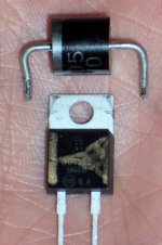
The diodes should be installed as in attached pic (the stripes mark the metal tabs):
So, this one (post #6)
http://img244.imageshack.us/img244/4342/wiring1ra.jpg
is not correct?
Yes, I believe those diodes in that post are not correct.
that picture needs to be wiped from the internet........
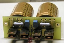
yeah! those diodes were put the wrong way!!! There are black lines on the board that are the metal side of those diodes, as Peter explain in the post above.😉
- Status
- Not open for further replies.
- Home
- Amplifiers
- Chip Amps
- Audio sector gainclone.