I found the LS25 circuit diagram from the product service manual.I want to clone this amp.From this circuit,only remark the part number for FET input device.Which transistor device can substitute it should be better.Pls give you advise,I am so appreciate your response.
Attachments
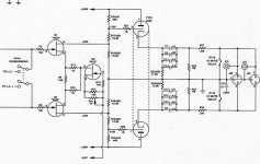
2SK170 should work, but you might have to select them for a particular Idss or adjust some of the resistor values.
You would also have to match the two input devices very well, preferably at more than one gate-to-source voltage, to make sure of both DC and AC symmetry.
J309 might work but you might need to reduce the power supply somewhat, to make sure the 25 V rating isn't exceeded.
Please double check the current ratings before taking any of my suggestions; I admit I haven't done any exact calculations here.
Another one to look at: 2N5459. Again, check voltage and current ratings. But that one may not have high enough transconductance.
Basically you want a high transconductance FET with low noise and sufficient voltage and current handling capability.
Please post or email me the rest of the schematic: I'll look into it further and will do some calculations.
Do you have the schematic for the first version of this line stage? This one appears to be for the Mk II LS-25.
-- mirlo
Hi Mirlo,
could you not get around the jfet matching by using 2sk389?
I read a review about the LS25 and it claims that it uses 4 X 6922 tubes?
Is this the circuit for the MKII?
Adams_Leo, wheres the PSU🙂
could you not get around the jfet matching by using 2sk389?
I read a review about the LS25 and it claims that it uses 4 X 6922 tubes?
Is this the circuit for the MKII?
Adams_Leo, wheres the PSU🙂
Amazing such a simple preamp costs US$5K. Reviews are very favourable. This looks like a good diy clone candidate, what does the pot RV1 do?
Luke said:Hi Mirlo,
could you not get around the jfet matching by using 2sk389?
I read a review about the LS25 and it claims that it uses 4 X 6922 tubes?
Is this the circuit for the MKII?
Adams_Leo, wheres the PSU🙂
Yes,this circuit for MKII,sorry,i cannt found the PSU
Luke said:Amazing such a simple preamp costs US$5K. Reviews are very favourable. This looks like a good diy clone candidate, what does the pot RV1 do?
RV1 set the bias for the input stage, with the Q3 current generator.
I'm working to build something like this, but with valves in the input stage, and resistor to set the bias
sajti
I calculate the power dissipated in the top (40K) resistor to be 109 watts Am I right, is the shematic wrong or does p=I2r not apply in vintage circuits😀
BTW Adams_Leo,
you ever build this?
Am I right, is the shematic wrong or does p=I2r not apply in vintage circuits😀 BTW Adams_Leo,
you ever build this?
Luke said:I calculate the power dissipated in the top (40K) resistor to be 109 watts
BTW Adams_Leo,
you ever build this?
((180-70)/40K )^2 x 40K = 0,3025W
pretty much less than 109W

I had a feeling I would embaress myself with that post.
I got 110 v drop across the resistor so current from v=ir is .0524A then used p=I2R and I allready see what went wrong🙂
Thanks for help with the math guys.
I got 110 v drop across the resistor so current from v=ir is .0524A then used p=I2R and I allready see what went wrong🙂
Thanks for help with the math guys.
I'll second that Steve. 😀
Luke, to calculate the power all you need here is Vsquared divided by R. which works out to be about 0.3W. The supply voltage is 180V (given) the voltage at the grids of the 6H30 is 70V (given) so the difference is 110V, square that and divide by 40K to get the power dissipated in that resistor.
Luke, to calculate the power all you need here is Vsquared divided by R. which works out to be about 0.3W. The supply voltage is 180V (given) the voltage at the grids of the 6H30 is 70V (given) so the difference is 110V, square that and divide by 40K to get the power dissipated in that resistor.
LS25MKII
Hello,
I built a clone of the LS25MKII ARC with the schematic of the post #1.
The working is very correct.
A simple calculation shows that tensions mentioned on this schematic (+ 70V and +20V) are false if HT = +180V.
If +20V on drains of the Fets, one cannot have +70V (Grid of the 6H30) but rather +60V
If +70V on grids of the 6H30, one cannot have +20V on drains of the Fets.
For the LS25MKII, AudioResearch Corporation says:
RATED OUTPUTS: maximum balanced output capability is 40V RMS at less than 0.5% THD at 1kHz).
On my clone, I have approximately only 20V RMS as maximum balanced output capability
Is there a modified version of this schematic that provide in balanced output 40V RMS ???
regards
jlm
Re: LS25MKII
Hi Jlm,
I am buliding a clone of the LS 25mkII.
Which fet did you use in the input stage and in the current source?
Regards
Riccardo
jlm said:Hello,
I built a clone of the LS25MKII ARC with the schematic of the post #1.
The working is very correct.
A simple calculation shows that tensions mentioned on this schematic (+ 70V and +20V) are false if HT = +180V.
If +20V on drains of the Fets, one cannot have +70V (Grid of the 6H30) but rather +60V
If +70V on grids of the 6H30, one cannot have +20V on drains of the Fets.
For the LS25MKII, AudioResearch Corporation says:
RATED OUTPUTS: maximum balanced output capability is 40V RMS at less than 0.5% THD at 1kHz).
On my clone, I have approximately only 20V RMS as maximum balanced output capability
Is there a modified version of this schematic that provide in balanced output 40V RMS ???
regards
jlm
Hi Jlm,
I am buliding a clone of the LS 25mkII.
Which fet did you use in the input stage and in the current source?
Regards
Riccardo
Go to http://www.arcdb.ws/
down the page...
click Linestages...
down the page...
click LS25...
There are circuit diagrams for Mk1 (four tube version) and Mk 2 (FET input version).
Enjoy...
down the page...
click Linestages...
down the page...
click LS25...
There are circuit diagrams for Mk1 (four tube version) and Mk 2 (FET input version).
Enjoy...
Darry said:2SK170BL
Thanks Danny for the replay.
You used the 2sk170bl for the input stage and also for the currente source?
Regards
Riccardo
Darry said:
Thank You Darry,
my last questions concerning the polarization of the input stage:
Which bias point did you use? Did you measure the gain of the stage?
Thanks again
Regards
- Status
- Not open for further replies.
- Home
- Amplifiers
- Tubes / Valves
- audio research LS25 preamp