Hello to all friends of the forum and well found
sorry my english but i am using google translator from italy
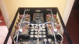
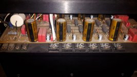
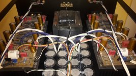
As can be seen from the title I have a problem with this ARC HD220 amplifier, the amplifier sounds good but heats up a lot, and the protection intervenes randomly, sometimes after half an hour sometimes after hours and hours of operation, both at low volumes and also at high volumes, I looked for the services manual to see if there is a bias / offset adjustment but I could not find any documents, opening the amplifier you immediately notice the two power boards L and R (I attach photos) completely separate and well anchored, from what I understand they mount 12 thermo tracks for each side, I do not know this type of Fet / transistor very well so I ask for help from you more experts, I also notice that the pcb lacks the screen printing of the component so I am not even sure if there is a services manual, at the input of the two boards I notice a small trimmer but I'm not sure if it belongs to the bias or not, thanks to all in advance I hope you can give me some good advice
sorry my english but i am using google translator from italy
As can be seen from the title I have a problem with this ARC HD220 amplifier, the amplifier sounds good but heats up a lot, and the protection intervenes randomly, sometimes after half an hour sometimes after hours and hours of operation, both at low volumes and also at high volumes, I looked for the services manual to see if there is a bias / offset adjustment but I could not find any documents, opening the amplifier you immediately notice the two power boards L and R (I attach photos) completely separate and well anchored, from what I understand they mount 12 thermo tracks for each side, I do not know this type of Fet / transistor very well so I ask for help from you more experts, I also notice that the pcb lacks the screen printing of the component so I am not even sure if there is a services manual, at the input of the two boards I notice a small trimmer but I'm not sure if it belongs to the bias or not, thanks to all in advance I hope you can give me some good advice
Attachments
-
 WhatsApp Image 2021-06-12 at 00.35.41.jpeg136.4 KB · Views: 332
 -
 WhatsApp Image 2021-06-12 at 00.37.31.jpeg127.3 KB · Views: 267
 -
 WhatsApp Image 2021-06-12 at 00.36.58.jpeg207.4 KB · Views: 263
 -
 WhatsApp Image 2021-06-12 at 00.36.38.jpeg264.2 KB · Views: 468
 -
 WhatsApp Image 2021-06-12 at 00.36.15.jpeg123.4 KB · Views: 347
 -
 WhatsApp Image 2021-06-12 at 00.36.00.jpeg187 KB · Views: 261
Those boards (with no solder mask or silk screen) are normal and typical for ARC products.
Suggest that you check the bias diode strings and connections. Those include R43 and R44.
Also check R29 and R30 and their related connections.
Audio Research HD-220 Stereo Power Amplifier Manual | HiFi Engine
Suggest that you check the bias diode strings and connections. Those include R43 and R44.
Also check R29 and R30 and their related connections.
Audio Research HD-220 Stereo Power Amplifier Manual | HiFi Engine
Last edited:
Thanks so much Rayma
What do you mean by solder strings or wire connections between boards? sorry but sometimes the translator is not very effective, which bias diode (diagram) are you referring to?
Without screen printing on the PCB and an agony intercepting the components .. could you visually point me out R29-R30-R43-R44-?
Are the resistors you mentioned in the power boards or on another board?
thanks again for everything
Yes, sorry. On the schematic, look for the R43 and R44 (each 43.2 ohms), and also R29 and R30
(each 1k ohms). They are part of a bias circuit. Each output transistor includes an internal bias diode.
You will have to locate these resistors on the power boards and trace out their connections. There are no
board pictorial diagrams however, so just look until you find them. There are not that many parts.
Since the bias diodes are in series, just one bad connection would cause problems with all of them.
Either the resistors are bad, or a connection is bad. Hopefully, the power devices themselves are good.
Last edited:
Thanks rayma ... update
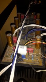
I did some soldering on the connections but to no avail, after which I started looking for the resistors mentioned, I state that it mounts all precision resistors with 6 colored bands, I understood that the polarization diode is inside each NJL3281D and NJL1302D so I attach also pin-out, looking first for R43 and R44 which as per drawing would be connected to pin 4 of the first two ic, I note that instead there is no r43 and r44 but in its place I find two diodes and subsequently R29 and R30 which are accurate to 1K, I do not understand if R43 and R44 are a schematic error I have a tamper, the two diodes are ok but how could you explain? Waiting for other advice thanks to all, I am attaching photos, the diodes do not seem to be mentioned in the diagram
I did some soldering on the connections but to no avail, after which I started looking for the resistors mentioned, I state that it mounts all precision resistors with 6 colored bands, I understood that the polarization diode is inside each NJL3281D and NJL1302D so I attach also pin-out, looking first for R43 and R44 which as per drawing would be connected to pin 4 of the first two ic, I note that instead there is no r43 and r44 but in its place I find two diodes and subsequently R29 and R30 which are accurate to 1K, I do not understand if R43 and R44 are a schematic error I have a tamper, the two diodes are ok but how could you explain? Waiting for other advice thanks to all, I am attaching photos, the diodes do not seem to be mentioned in the diagram
Attachments


Just locate the two bias strings and check for bad parts or connections.
That's about as far as we can go without an updated schematic.
That's about as far as we can go without an updated schematic.
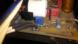
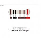
Hi guys, other welds have been redone but the problem still persists, checking the connections I notice a slightly scorched resistance (I attach photo) measuring it is open no reading, one of the two ends is mounted on the frame and seems to be the only one positioned on the frame, looking the diagram could be a 10 ohm R119, but I would not make any mistakes given the high voltages, I wanted to ask you about whether the trimmer (photo first post) from the 5k RV1 diagram would need less bias adjustment or not, some good core Could you confirm that it is indeed R119? thank you all
I was lucky enough to own one of the ARC reworked HD220s with the current 3281DG parts vs the old discontinued part that is known to have problems. I have heard stories of these things going to shutdown mode due to
1.) the output DC detection circuit sensing excessive DC
2.) current hogging by one of the ONSEMI devices causing 1 device to heat up excessively.
May I suggest checking the input to the solid state portion ie the output of the couplingcap to make very sure the 4uF cap is not leaking small amountsof DC causing the amp to go out of whack first
Then perhaps getting a logging device and hook it at the speaker output to see if the thing emits DC before going to protection
I did quite a bit of mods to the tube section and have great results (got rid of the JFET stage and rebult the gain stage into a tube-only classic long tail pair diffamp) but thats a different discussion.
Cheers and best of luck.
- Home
- Amplifiers
- Solid State
- Audio Research hd220 bias problem (random protection)