Im still not understanding why the input wiring to the right channel is melted, theres zero current running here under normal operation any input on that ?
The signal wiring? This may indicate your source ground potential was different to the amp's. All sorts of reasons for that: a leaky mains transformer, poor grounding... Only this does not explain the failed output transistors.
I don't know much about thermaltracks. These ones carry a designation of conventional transistors, only with compensation diodes. All the compensation diodes are in series and perhaps the failure of one may have caused the bias to jump up. Do these diodes ever fail?
Haven't seriously examined the circuit and perhaps will not understand their motives anyway. A diamond buffer afaik has a stable enough bias without any additional thermal compensation. The thermaltracks appear an unnecessary complication. Are they used to prevent thermal runaway or to make sure the amp runs at constant bias at all temperatures?
For the record - if you read the OP - I did play the amplifier for about 30 minutes after repairing it - it sounded great.
Good Listening
Peter
Good Listening
Peter
Were they the Thermonetics inrush limiters? -- if so they will get really hot IF the current is kept LOW for two long a period of time.
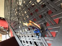
Did a little more investigating - to try to figure out why the input wire melted - the isolation on the wiring is flammable, strange choice for use in an amplifier. So the input wiring got ignited by the burning wiring below.
I'm certain the failure was caused by high frequency oscillation in the right channel - spilling over to the left channel as they share a common power supply. The output trannies on the left channel are still intact.
Thank you to all for input on this - going to gut the chassis and possibly put another amplifier in it at one point.
Good Listening
Peter
Attachments

Were they the Thermonetics inrush limiters? -- if so they will get really hot IF the current is kept LOW for two long a period of time.
The exact reason i don't like to use fixed resistors as inrush limiters, a inrush limiter do get hot but its designed to do so and it can carry the current without exploding.
The exact reason i don't like to use fixed resistors as inrush limiters, a inrush limiter do get hot but its designed to do so and it can carry the current without exploding.
Attachments
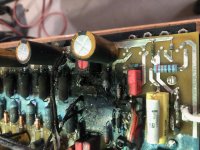
"The output trannies in the Left channel are still intact" -via-a-vis the Right channel output devices are blown---typical fault in a high frequency oscillation overheating them ,seen it time and time again --ergo heavy current applied due to extreme signal helped by large bank of high value capacitors inputting very high current .
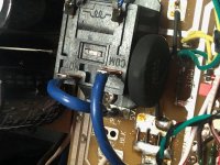
See the browning on the mains transformer ?
Looks like a blown transformer .
See the browning on the mains transformer ?
Looks like a blown transformer .
Again, if one of the thermal diodes opens up, will not all output transistors in that channel overbias and overheat?
Would one of the oscillation theory fans explain what causes oscillation in a unity gain buffer? Perhaps a purely capacitive load can indeed do it, but a short at output is a lot more likely.
Would one of the oscillation theory fans explain what causes oscillation in a unity gain buffer? Perhaps a purely capacitive load can indeed do it, but a short at output is a lot more likely.
Analog_sa - if its not oscillation why the left channel wiring melted too - suppose it could be from being ignited by the burning wiring to the right channel - just like the input wiring to the right channel ? Perhaps a shorted output like you mention ? A set of fuses sure would have been proper implementation.
Good Listening
Peter
Good Listening
Peter
Oscillation is often proposed when people are just baffled. And at this stage we can really only guess.
When something as sturdy as a 35amp bridge blows up there is always a serious reason. It is also the appropriate time to take measurements and scratch your head. Perhaps the manufacturer could have made things more indestructible but this is always balanced with sound quality. Once you have fuses and relays all over the place you may not really want to listen to it any more.
When something as sturdy as a 35amp bridge blows up there is always a serious reason. It is also the appropriate time to take measurements and scratch your head. Perhaps the manufacturer could have made things more indestructible but this is always balanced with sound quality. Once you have fuses and relays all over the place you may not really want to listen to it any more.
I have nothing to contribute.
But if I had that mess to clean up, I'd be sitting in a corner rocking back and forth crying for mummy.
But if I had that mess to clean up, I'd be sitting in a corner rocking back and forth crying for mummy.
analog_sa
The original bridge was a 20A one - I replaced it with a 35A one. Since the outputs are no longer available ill just gut this thing and oput a real amplifier in it when I get the time.
I see nothing wrong with rail fuses I use them in my own designs.
Good Listening
Peter
The original bridge was a 20A one - I replaced it with a 35A one. Since the outputs are no longer available ill just gut this thing and oput a real amplifier in it when I get the time.
I see nothing wrong with rail fuses I use them in my own designs.
Good Listening
Peter
Attachments
Oscillation is often proposed when people are just baffled. And at this stage we can really only guess.
When something as sturdy as a 35amp bridge blows up there is always a serious reason. It is also the appropriate time to take measurements and scratch your head. Perhaps the manufacturer could have made things more indestructible but this is always balanced with sound quality. Once you have fuses and relays all over the place you may not really want to listen to it any more.
Baffled ??---as somebody who repaired 100,s of blown power amps I am not "baffled " .
It was pretty obvious when the output devices were blown taking out the drivers --massive overheating --resistors blackened --PCB blackened .
In only 2 occasions was it a faulty bridge rectifier .
Instead of using virtual reality to judge conditions of a design I used the old school method --scope at output -load on--old school variable -variactor -twin meters (analogue ) -variable small value capacitor in compensation position --slowly increase mains voltage--watch current meter --watch for growth of large HF oscillation -- increase capacitance--allow for safety margin etc .
Then there was component layout --quote- "it worked great on the breadboard but HF oscillation when transferred to self designed PCB "--courtesy of EW.
In my day you had to design the board yourself -- no computer assisted software and yes JLH used old school methods but what you got was a deep practical learning of potential fault conditions --emphasis on Practical .
So I will stick to what I actually came across not by staring into audio software .
Advertisers say their components are the best thing since sliced bread that wasn't always true but more so now with components "built to a price " to obtain the biggest profit .
I am not decrying audio software , yes it saves a lot of time but like the modern child who cant use mental calculation without asking ---"where,s the calculator " does this modern stuff really give you a deep insight into audio design ?
I learned the old way and --to me those "outdated methods " still work best.
So I will stick to what I actually came across not by staring into audio software
No idea what is "audio software" but it does sound terrible, especially if it makes you stare at it 🙂
Not at all strange, almost all wiring is flamable, but wiring should always be protected from overcurrent by a fuse or such anyway. You can use silicone insulated for wire intended to be pushed hard, but its usual to pick thicker wire instead and a suitable fuse. Teflon insulated wire will also tolerate much heat, but the fumes are pretty toxic once it chars.the isolation on the wiring is flammable, strange choice for use in an amplifier.
In special circumstances non-flammable insulation is mandated (usually for fire regulations in building ducts, aircraft etc). Its more expensive and harder to use.
And another point to consider - if the wire gets hot enough that the insulation starts to char, its going to melt any solder joints, so just assuming a robust enough insulation solves the underlying problem isn't really valid. As wires heat up their resistance increases quite
a lot too, potentially leading to thermal-runaway (acting as fuse). Wires that run cool are best. Size the wire, size the fuse, job done.
Last edited:
The original bridge was a 20A one - I replaced it with a 35A one.
The service manual has a 35A part listed. Not that it makes a huge difference
Since the outputs are no longer available ill just gut this thing and oput a real amplifier in it when I get the time.
Choosing the easy way out? The outputs are available, albeit at a price. They can also be emulated with diodes, or the circuit can be adjusted slightly to use standard transistors. Gutting is for sissies 😀
"Not at all strange, almost all wiring is flamable"
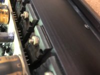
This wires insulation burns way way too quickly - if you look at the control wiring it charred too but only a few inches, the power wiring and the input wiring ignited then burnt with out any self extinguish properties.
"Choosing the easy way out? The outputs are available, albeit at a price"
These devices have quite a bad wrap, and the clean up would be quite extensive on the right output stage. better to just gut it and put in something that works 🙂
Good Listening
Peter
I think i have figured out what happened with this one.
One or more of the Thermal Track devices on the right failed, it caused the board to heat up so much it caught the insulation on the wiring on fire. The insulation on this wire is not self extinguishing so it caught the rest of them on fire. If you notice in pictures above - the control wiring only charred about an inch or so on either side of the burning insulation below.
The initial conclusion that the wires over heated because of oscillation or other is not correct. It started at the Right channel PCB were the power wires enter it then spread to the rest of them.
Good Listening
Peter
Oscillation is often proposed when people are just baffled. And at this stage we can really only guess.
When something as sturdy as a 35amp bridge blows up there is always a serious reason. It is also the appropriate time to take measurements and scratch your head. Perhaps the manufacturer could have made things more indestructible but this is always balanced with sound quality. Once you have fuses and relays all over the place you may not really want to listen to it any more.
If he also made repairs to the soft-start circuit, that could be a reason to expect a blown bridge. If the contacts on the soft-start relay were welded closed, for example. Without a soft-start circuit, 200,000 uF of capacitance is more than enough to blow a bridge.
Of course, if the soft-start relay was failing to close, then one should be even more concerned about a blown bridge rectifier.
All of this aside, any amp that can set itself on fire if the output devices fail is dangerous. There is zero excuse to not have some form of rail fusing. In an amp with such a stupid power supply (200,000 uF, no?), a transformer primary side fuse isn't really enough.
That said, a more pressing issue is why the mains fuse in the amp didn't blow. Did someone replace it with an inappropriate value? That's always something to check.
I wouldn't gut the amp unless it's truly destroyed. That is a pretty cool amp when it works, and worth a pretty penny. Check if the transformer is blown, then work your way through. This was almost a $10,000 amplifier when it was introduced less than 20 years ago. I wouldn't gut it unless it is really, really destroyed. AR isn't a stupid company- they tend to come up with good designs. This one may have had inadequate protection (or it was defeated by someone with a 30A fuse), but that can be corrected. In an amp that is potentially worth several thousand dollars, blown output devices and a bit of burned wiring is not necessarily reason to deem it irreparable.
When this kind of thing happens, the right thing to do is to go through it one thing at a time. Clean the soot off and assess the damage. First off, is the transformer okay? This is an easy enough test. If the answer is no, this can be dealt with, assuming there isn't too much other damage. Is the PCB salvageable? You won't know until you clean all of the soot off. It probably isn't as bad as it looks. If it is beyond repair, can you replace it? You might be able to get parts from AR.
It's good practice for when you run into this kind of thing in the field. Sometimes a few hours of careful investigative work can save $50,000 of unnecessary replacement costs.
A quick search of the web has at least one owner complaining about the Thermal Track devices causing problems with his amp. He says ARC would not repair it and tried to upgrade him to another amp, saying the amp was unrepairable. Things spiral from there.
I don’t believe everything I read on the web. But it does sound like there may be a problem with those devices.
I don’t believe everything I read on the web. But it does sound like there may be a problem with those devices.
The Thermal Trac outputs definitely have issues, there's newer replacements, its been stated they don't work in this circuit. I brought the issue to AR, the one with the flammable wiring, this is the real danger with this design, if in a cabinet this could easily have caused a fire. It was blown off. The rail fuse did blow, 8A slow blow, but not soon enough to prevent the ignition.
Rail fusing surely would be a prudent thing in this amplifier.
Good Listening
Peter
Rail fusing surely would be a prudent thing in this amplifier.
Good Listening
Peter
- Home
- Amplifiers
- Solid State
- Audio Research HD 220 up in flames