Could be that the capacitors of the 2k-20k range have gone bad (or the relays that switch them). I think these are through-hole polypropylene types, ~3.33 nF.
Does the THD+N function work properly in that frequency range?
Samuel
Does the THD+N function work properly in that frequency range?
Samuel
Dear Samuel,
thanks for your reply. No, the TDH+N is not working properly in the 2k-20k range. I guess the bandpass is necessary for this measurement.
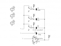
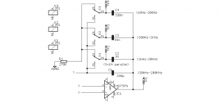
I have made some investigation regarding your notes (which is very laborious, because I have no schematic from SYS Two; the service manual of SYS One helps a bit for understanding some functions...). The attached schematic shows what I have realized ( I hope I’m right); a part of an integrator. There are obviously four integrators on board, similar to SYS One.
1) In the 20.5k - 200k, range all is fine and TP2,TP3,TP4 has roughly the same voltage as at TP1 (same at the other 3 integrators)
2) In the 10Hz-204Hz range the voltage at TP3 and TP2 is similar to TP1. I guess that makes sense, because C4 is working and TP4 is virtual grounded (same at the other 3 integrators)
3) In the 205Hz-2347Hz range the voltage at TP2 and TP4 ist similar TP1..ok
4) Now in the “bad range” 2k-20k the voltage at TP1 is around 0 V !! It seems that the Inv.-Iput and the Output of IC1 is shorted ??! The accordingly TP1 at the other 3 integrator has signal; around 10dB less compared to the voltage in the “working” frequency ranges.
Unfortunately I have no schematic and I do not understand what is going wrong.
Do you have an idea ?
Best regards
Michael
thanks for your reply. No, the TDH+N is not working properly in the 2k-20k range. I guess the bandpass is necessary for this measurement.
I have made some investigation regarding your notes (which is very laborious, because I have no schematic from SYS Two; the service manual of SYS One helps a bit for understanding some functions...). The attached schematic shows what I have realized ( I hope I’m right); a part of an integrator. There are obviously four integrators on board, similar to SYS One.
1) In the 20.5k - 200k, range all is fine and TP2,TP3,TP4 has roughly the same voltage as at TP1 (same at the other 3 integrators)
2) In the 10Hz-204Hz range the voltage at TP3 and TP2 is similar to TP1. I guess that makes sense, because C4 is working and TP4 is virtual grounded (same at the other 3 integrators)
3) In the 205Hz-2347Hz range the voltage at TP2 and TP4 ist similar TP1..ok
4) Now in the “bad range” 2k-20k the voltage at TP1 is around 0 V !! It seems that the Inv.-Iput and the Output of IC1 is shorted ??! The accordingly TP1 at the other 3 integrator has signal; around 10dB less compared to the voltage in the “working” frequency ranges.
Unfortunately I have no schematic and I do not understand what is going wrong.
Do you have an idea ?
Best regards
Michael
Attachments

TP2 trough TP4 should be at ground potential all the time, either enforced by the virtual earth or the relay connection to ground.
TP1 should show the signal. What do you mean by "TP1 is around 0 V"? What is the exact voltage/signal at this point?
As noted C2 or K1 could be damaged.
Samuel
TP1 should show the signal. What do you mean by "TP1 is around 0 V"? What is the exact voltage/signal at this point?
As noted C2 or K1 could be damaged.
Samuel
Dear Samuel,
thanks again for you reply.
TP2-TP4 are not directly at ground potential (maybe pull down by a 100k resistor) all the time in SYS One and in the 3 integrators of SYS Two.
In the 20.5k - 200k, range all is fine and TP2,TP3,TP4 has roughly the same voltage as at TP1 (same at the other 3 integrators), only C1 is working.
Why should TP2 through TP4 be at ground potential ? Please explain.
The Voltage at TP1:
80mVp/3kHz; 4Vp/100Hz; 4Vp/2kHz; 4Vp/100kHz
Michael
Correct, the relays can't switch directly to ground, of course, but probably do through a resistor. So the caps are at DC ground, but not AC.
Is the generator frequency (measured with the analyzer) correct in the 2-20 kHz range?
Samuel
Is the generator frequency (measured with the analyzer) correct in the 2-20 kHz range?
Samuel
Yes, relay or capacitor is a likely cause, as noted before. Make sure to check all integrators.
Samuel
Samuel
If you have the time I'd be interested to see what components (in particular series elements with the negative input or shunt elements at the output) connect directly to the AD797.
This opamp is not directly stable with that much feedback capacitance, so they must have used some sort of aid. A simple one is a ~150 Ohm resistor in series with the negative input, but that adds noise. An inductor in parallel could solve this.
Samuel
This opamp is not directly stable with that much feedback capacitance, so they must have used some sort of aid. A simple one is a ~150 Ohm resistor in series with the negative input, but that adds noise. An inductor in parallel could solve this.
Samuel
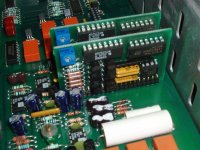
Ah, your AP still has silver mica caps in the higher range--these are brittle and may break (as probably happened here). Later they used ceramic C0G, a much more reliable dielectric.
I have no detailed info on the circuit of the MDAC. Probably the AD7523 is used for the lower bits, and discrete JFET switches (PN5432?) for the higher bits.
Samuel
I have no detailed info on the circuit of the MDAC. Probably the AD7523 is used for the lower bits, and discrete JFET switches (PN5432?) for the higher bits.
Samuel
Audio Precision System Two GENERATOR PROBLEM
Are you still having the problem? I can help you.
Duke
Hi all,
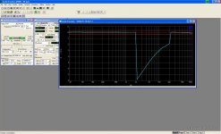
the system check of my Audio Precision System Two shows a fault in the band-pass test. In the area between 2.05 kHz and 20.47 kHz the gain differs around 8dB with a strange slope (see picture). Can anyone help or has a wiring diagram?
Are you still having the problem? I can help you.
Duke
- Status
- Not open for further replies.
- Home
- Design & Build
- Equipment & Tools
- Audio Precision System Two Repair