Hi everyone,
I need some expert help on a nasty System One sweep graph problem.
I just recently acquired a 2nd hand Audio Precision System One, Typ 322. I've been using S1's before a bit though.
The 322 runs with an USB adaptor by Udo Krebelder (AP compatible USB adapter) under APWin 2.24 on Win10.
It works well and I am happy with it, apart from one issue:
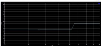
The problem I have relates to sweeps - whatever I do, regardless of any settings in the settling panel (although I admit not all of those are intuitive to me), I get a -1.9dB step in the frequency response. See attached screenshot. This is disturbing when documenting measurements as it always looks like there is a problem while nothing is wrong.
I have verified with an external mV Meter and an external generator that both the generator and the analyzer of the 322 show correct readings over the full 20Hz-20kHz range. So I don't think this is a hardware problem.
Anybody being expert enpugh to point me in the right direction for a solution?
Thanks in advance, Dirk
I need some expert help on a nasty System One sweep graph problem.
I just recently acquired a 2nd hand Audio Precision System One, Typ 322. I've been using S1's before a bit though.
The 322 runs with an USB adaptor by Udo Krebelder (AP compatible USB adapter) under APWin 2.24 on Win10.
It works well and I am happy with it, apart from one issue:
The problem I have relates to sweeps - whatever I do, regardless of any settings in the settling panel (although I admit not all of those are intuitive to me), I get a -1.9dB step in the frequency response. See attached screenshot. This is disturbing when documenting measurements as it always looks like there is a problem while nothing is wrong.
I have verified with an external mV Meter and an external generator that both the generator and the analyzer of the 322 show correct readings over the full 20Hz-20kHz range. So I don't think this is a hardware problem.
Anybody being expert enpugh to point me in the right direction for a solution?
Thanks in advance, Dirk
Attachments
Dirk, did you do a loop back measurement to be sure it's the AP?
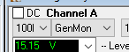
On the analyzer panel, select GenMon as input.
Also, does it appear in only one channel or both channels?
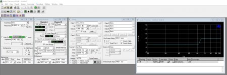
Can you show a screen shot of the analyzer, generator and sweep panels?
Jan
On the analyzer panel, select GenMon as input.
Also, does it appear in only one channel or both channels?
Can you show a screen shot of the analyzer, generator and sweep panels?
Jan
Attachments
Last edited:
Hi Jan, thanks for looking at this so swiftly, very appreciated. Indeed, I've done both a "hardwired" loop-back as well as an internal one by the GeneratorMonitor, the result is the same. See attached the expanded panels in GenMon setting. The graph is reduced to the "wrong" area, that why the upper sweep frequency is only set to 100Hz. It does the same on both channels.
Attachments
Bummer. If it is on both channels it points to the section that they have in common, which are the reading and filter circuits.
In the analyzer panel, can you set the reading function to bandpass instead of amplitude?
Does that make a difference?
Also, do a 2-channel sweep, both channel A and B. If it is in the common area, the two graphs should be the same.
Jan
In the analyzer panel, can you set the reading function to bandpass instead of amplitude?
Does that make a difference?
Also, do a 2-channel sweep, both channel A and B. If it is in the common area, the two graphs should be the same.
Jan
Last edited:
Hi Jan, many thanks again. Based on your advice, I have played a bit around with the BP/BR parameters. I was initially not sure whether this would do anything as I verified before with a mV meter that the generator did constant level in the whole band, and I likewise used an external generator to feed the analyzer and found it to have constant readings over the whole band as well. Since the hardware filters were inside the signal path during these tests, I should have seen the same problem. Nevertheless, playing with the settings...I found that once I set the detector to anything else but AUTO, the problem is gone. Once I set it back to AUTO, the problem returns. I read that the AUTO parameter is calculated by APWIN, not by the S1. So its most likely a PC-side problem, or maybe a problem with the USB interface (which I initially regarded as the least likely). I shall get in touch with Udo Krebelder and see what he says...so...I am a step further, thank you!
I don't think it is in the PC because that's just software that reads the hardware values and does some number crunching. It gets the bad data from the S1.
The AUTO is not something that is calculated, it is a hardware setting (you probably hear some relays clicking when you play with that setting).
Do you have the schematics package?
Jan
The AUTO is not something that is calculated, it is a hardware setting (you probably hear some relays clicking when you play with that setting).
Do you have the schematics package?
Jan
Hi Jan, yes I do have the schematics package. Page 223 of the service manual I have (Rev 4.0 of Dec 1992) refers to the detector resolution, but it does not make any statements towards the AUTO function's implementation. Page 239 shows the V/F converter (U341) while the "DETECT" rate seems to be determined via the clock supplied to U321 (a 74HC374). This itself seems to come from U241 (a 74HCT139) on page 225 of the service manual. This then directs to the mainframe...I can't see any relais on the mainframe boards schematics though, and I also have no relay clicks upon making settings in that section of APWIN. If any relays should be involved then this could hint towards the problem. Do you have any specific relay under suspicion?
I'll see if I can find my schematics. In some positions that have no effect on distortion, they use solid state switches like the CD4053 or equivalent.
If you look at the step in the response, which level is the correct one, the lower or the higher?
Jan
If you look at the step in the response, which level is the correct one, the lower or the higher?
Jan
- Home
- Design & Build
- Equipment & Tools
- Audio Precision system one sweep graph problem