I've got an AP Sys 1 and the loopback distortion gets very high at low frequency. At 20Hz it is 0.22% and it decreases at about 20dB/decade so by 2kHz it is normal around 0.002%. I tested the generator with another analyzer and the generator is fine at about 0.001% at 20Hz. So I'm pretty sure the analyzer is have trouble. The other clue is both the A and B analyzer channels have the same distortion problem.
Any ideas whats going on?
Any ideas whats going on?
Check the "Reading" Monitor Output. This may give you a clue as to what is causing the abnormal readings. Mine picks up noise if I set a monitor on top of the unit. Also could be the fundamental is not fully nulled out.
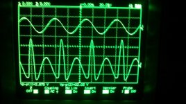
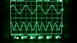
I found that if I left it sitting for long enough it would slowly settle down. So after about 2 hours it finally got down to about 0.002%. The waveforms I've attached were taken just after I turned it on. Top trace is Input A Monitor, and the bottom trace is the Reading Monitor. The one with the tall spikes is 1Vrms 20Hz and it read a distortion of about 1%. The second was at 10Vrms and the distortion was 0.05%. These are all done reading the GenMon. Thoughts? Any help is appreciated.
Attachments
My first thought would be to look at biasing of the output buffer, but crossover distortion should affect more than just low frequencies. You might try looking upstream towards the oscillator to see if distortion occurs there.
Edit: there is an adjustment R4601 "20Hz THD".
Edit: there is an adjustment R4601 "20Hz THD".
Last edited:
I went through to find where the distortion is introduced into the system and it isn't all the way until the bandpass filter section of the distortion board. I'm not sure how to go about diagnosing that section, I think I'll get a can of compressed air and see if any of the components are temperature sensitive.
Where is the 20Hz THD pot at? That sounds like it could be it.
Where is the 20Hz THD pot at? That sounds like it could be it.
Sorry, that adjustment is on the generator side. Re-reading your original post it would seem that the problem is on the analyzer side.
I fired up my Sys 1 last night and I would like to know exactly the settings you used for the scope shots above. I just set the Analog Analyzer input to "GenMon" and looked at the scope outputs. At 20Hz the Reading output was all noise. Generator amplitude had no influence but THD+N rose at low amplitudes. No 2nd harmonic or crossover notch. Filters were set to <10Hz, >500KHz.
nickm1,
Late to this party, but I thought this might be of some help:-
Yesterday I powered up one of my AP1's for the first time since retuning from China 3 years ago, only to find a similar problem with THD+N, it was jumping about from 0.003% to 0.1% 20Hz-22KHz (GenMon) ... So I put it to once side and powered up a second unit only to find other problems and then with a 3rd unit! Yesterday was a REALLY bad day.
So I spent the day looking into the issues on these units - all would fail the selftest routines (the little "Red" tick box in APWIN 2.24), THD, Level and Phase depending upon unit.
The THD problem was due to Electrolytic capacitors leaking on the PCB manufactured by NIC Corporation NRWA series 25V / 47uF Dark Brown Body.
NIC Components NRWA Series
You need to look closely at every PCB in the unit as there are two types manufactured by NIC, Dark Blues types which don't appear to suffer from the issue, but I remove 23 "Dark Brown" Caps from my unit, EVERYONE of them had leaked or showed signs of leakage.
https://dl.dropboxusercontent.com/u/86116171/AP1 Cap1.JPG
https://dl.dropboxusercontent.com/u/86116171/Section AP1 Cap2.jpg
https://dl.dropboxusercontent.com/u/86116171/AP1 Cap2.JPG
https://dl.dropboxusercontent.com/u/86116171/AP NIC NRWA bad Caps.jpg
Unfortunately the electrolyte had almost eaten though the Copper tracks on one of my DIS boards, lucky I caught it just in time.
Basically after cleaning the PCB and replacing all the caps resulted in stable THD readings, but I had to readjust the Null and Level pots to achieve a deep notch (about -115dB to -120), slightly lower the the second harmonic component.
I'm not sure what THD+N at 1Vrms, GenMon, 20Hz to 22KHz is normal, but I was able to tweak to 1KHz 0.00035% (Non Wtd), this then drifted to 0.00045% when the covers where replaced.
After setting the Gen Level, Tweaked the Null and Level Pots in each DIS board Adjusted the Phase pot on one unit, I was able to get all units pass the selftest - WHEN WARMED UP, when first powered up non would pass - it takes about 10 minutes warm up period before the plots on the selftest start to appear they will fit within the Pass / Fail template "Masks".
I say all passed, but one unit would still fail the “Flatness test” at 20Hz, limit is 0.03dB, it failed at -0.035dB… I’ll not waste time hunting this down unless anyone has any ideas?
I also had to adjust the 20MHz Reference (really a poor design the clock frequency all over the place), I also had to adjust the 100Hz, 1KHz, 10KHz & 100KHz Gen frequency pots on the Gen boards, these had drifted on all units.
AP provide the full Calibration routes for the AP1 which I tried in the DOS box on a Windows XP machine but the program was SOOOO primitive (I remember DOS days, but NOTHING this primitive) I could not find the directory that had the procedure / .TST files saved and not knowing what I was really doing escaped back to the safely of the WinXP GUI and stroked my Trackball / Mouse thanking him that the DOS days are long past!
Lastly, a problem I’ve seen in China where one unit on a production line puffed out smoke and flames – the crimping connector on the White Cable from the transformers secondary should be soldered directly to the PCB as the connection overheats and browns / melts the plastic connector housing, ALL my units suffered from the same issue – its going to fail, so take the time to fix it when your replacing the caps.
Last edited:
- Status
- Not open for further replies.
- Home
- Design & Build
- Equipment & Tools
- Audio Precision Sys 1 Problem - Low Frequency Disortion