The THD+n measurement is best when the ratio between the peak to peak voltages output of bandpass and lowpass opamp is about 0.93
It is possible to manually tune the filter frequency and obviously it changes the voltage ratios and also the overall amplitudes if the input signal deviates from the supposed center frequency.
I also hooked up a logic analyzer to the mdac digital inputs.
In the regions switched by the tuning capacitors the mdac digital in goes from 819 to 8190 (when converted to decimal). When switching into the next tuning region the mdac digital in jumps back to about 819.
So practically one whole MDAC range for each tuning cap value.
If there is something wrong with the mdacs the problems would show quite far apart also it is possible that on lower ranges the potential mdac error is masked by the tuning and nulling loops.
If I observe the filter bandpass and lowpass out when the 20.5 threshold is passed I can see that the amplitudes jump and then the servo loops try to correct that. The <20.5kHz range corrects the voltages downwards and >20.5 region corrects them upwards (but obviously reaching the correction limit and not being able to reach the target voltage).
Funny thing is if set the generator to 20.5something and then manually tune the filter down a bit so it goes into the previous region, the null & tune loops manage to correct the mismatch and I get THD+n reading of 0.0019%
If I go back up to the correct frequency (switching into the next region in the process) the servo loops can't compensate anymore and the THD+n reading goes way up to max 0.151 % (when the operation temperature settles).
If I look at the output of the filter (input into the DAC which probably performs level measurements) I can see that there measurable fundamental frequency signal still left which was not filtered.
The MDAC modules on the schematics of S1 are listed as "MDAC hybrids" without any schematics. But in reality they are PCBs with an AD7523JN for the lower bits and discrete transistors with precision resistors for the upper bits (total 13 bits) (see the attached pic).
There is an undocumented trimpot on the module. I looked for images of S1 internals on the net and the MDAC module in S1 looked pretty much the same except there was no trimpot on it.
Curious thing is that when instrument is powered off the resistance between pin 1 and 2 is different between each MDAC modules. One measures 1.1kOhm the other one 1.5kOhm
I would expect that they should be more close. Since this is measured in circuit there could be something affecting the measurement, but since one pin is connected only to the op-amp input which should be quite high impedance, I would really expect that the MDAC modules are more similar. Especially since the integrator mica caps are 330pF each.
So it seems that until my replacement caps arrive (which probably won't solve anything) I'll have more fun with the MDACs. I'll have to make a test rig to power them and supply digital inputs so I can really measure what is going on internally.
Attachments
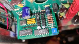
Very interesting that the MDACs are discrete modules. From the "hybrid" description I was imagining wire-bonded chip ICs on alumina substrate. The modules look they could be repaired if necessary!
The fact the digital codes vary by exactly a decade (819 to 8190) is cool! I'd anticipate similar decade ratios on each band though the start and end codes might vary to accommodate tuning cap tolerance. I doubt the tuning loop can push the filter center frequency more than a percent or so--- too much distortion otherwise.
Not sure what to make of the differing resistances you observe between the two MDACs. Do both appear to be stuffed with identical resistor values? It's possible the MDACs are scaled with different resistances to help establish the desired filter Q. I also agree that unpowered opamps are likely to present high resistance. But try exchanging ohmmeter leads to see if meter reading varies with applied polarity; variations imply there's junction conduction in play.
I agree that replacement NPOs are unlikely to cure anything.
Hi JakaBac
The MDAC is not the problem. Several years ago I found a problem that is similar. It was on a S1 where the 2k-20k band where the THD was good and bad vs frequency while other bands were GOOD. The problem was the Silver Mica cap was BAD. The system was Tom Holman’s. He used the cap in his Electronic Film class @ USC. The cap passed the basic capacitor tester, how it leakage was about 113K ohms. This caused the servo loop in the THD circuit to become unstable @ various frequencies. The Silver Mica had Silver migration / oxide from a fractured seal on the lead as it cracked during installing assembly or over time.
I had this posted on the “LinkedIn, Classic AP Audio Systems Group (Old group that can’t be updated).
The P1 circuit is similar and could have the problem.
Duke
Many years ago I spent a week troubleshooting a leaky mica cap in the input circuit of an HP AC volt meter. Tube input and everything was high Z and I could not see where the leakage was until I disconnected the cap. It did not measure as leaky and you just don't think of those breaking like that. Those are really difficult problems to solve.
Thank you, Audio guys!
So it's likely the mica caps after all! And I knew from bitter experience that leaky parts can be noisy parts.
Now that I scrutinize Jaca's sweep waveform more closely, I can see vestiges of the high band problem in the next lower band as well--- just attenuated by a good 10X cap paralleling the noisy mica. The evidence was there, but I didn't see it. 🙁
Thanks again.
I've seen the mica caps go noisy in the miller feedback cap position of a couple of preamps I've worked on. Last year I had a pre with one channel in which distortion was like 10 - 12dB worse than the other at elevated output voltages. How I found the problematic component was by putting my soldering iron tip up against the mica cap and heating it while watching the distortion on the AP. The distortion dropped substantially once the cap was heated. After replacing the mica cap the two distortion curves were nearly identical.
I found the two AP graphs of the before and after replacement of the mica cap I spoke of earlier. These were 1kHz tests.


I already ordered replacements, but since they checked out fine out of circuit I was doing some more investigation until the parts arrive. Local shops don't exactly have 330pF 1% silver mica caps on stock 😉
Anyway I learned a bit more how the MDAC works in the meantime.
When looking at the S1 schematic first time before delving into the internals of P1. I was also thinking that MDAC hybrid will be a magic unobtanium box in exotic packaging which renders the equipment useless when it goes bad 🙂
Thanks a lot for all your help! I'll keep you posted on the replacement results.
Also if in the future anyone wants me to measure something on my P1 to help his/her troubleshooting just give me a shout.
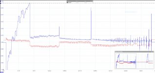
After changing the two 330pF mica tuning caps the P1's THD+n is stable in the 21-20.5kHz area even after 1h of operation.
The null control voltage is still quite high in the 20.5kHz+ decade, but in the problematic 21kHz-20.5kHz area the opamp still has some headroom to its positive rail.
The attachment shows tune and null voltages after mica change and warmup (keep in mind if you compare this with my previous graph that on the previous graph the null voltage has a -4V offset applied by the oscilloscope so I could capture the interesting part of the signal).
The two micas out of circuit do not show ANY signs of problems or malfunction. under a microscope no cracks or anomalies could be seen. The DC resistance measures as open circuit and they pass LCR tester with flying colors (tested at 10,100,1kHz,10kHz and 100kHz). Capacitance well within 1% and dissipation factor is 0.0007 (both of them).
Heating them with hot air has insignificant effect on the LCR measurements.
But obviously changing them fixed the problem.
I am really curious what measurement could be performed on the two mica caps to make the fault evident.
The THD+n however is still a bit higher on the 20.5kHz+ range. (0.0023% vs 0.0012%) I don't know if this is design's limitation or something is still off. But at least everything is stable now.
Even if I consider the problem as fixed for now, if someone has a recommendation for something else to be changed, I would be happy to do that 😀
Attachments
Last edited:
Here are my own tests from a couple years back showing the step change @20.5kHz+.
My own differences back then in measured distortion between channels was due to cheap cables.
My own differences back then in measured distortion between channels was due to cheap cables.
I harbor a suspicion that the reason residual distortion seems to rise with increasing frequency (abruptly at band edges) is inherent in state variable oscillator (SVO) designs that (invariably?) use the low-pass integrator for ouput.
Bob Cordell’s Audio Magazine article describing his THD analyzer has an excellent exposition of the merits of the SVO design. Chief among several advantages is that the LPF integrator filters distortion from the ALC at 40dB/decade.
IMO, one of the few disadvantages of the SVO is that the LPF output has noise bandwidth that grows directly with operating frequency; its noise equivalent bandwidth extends from 0Hz to somewhat above the oscillation frequency. I believe this characteristic underlies much of residual output in SOA analyzers featuring SVOs--- that is, much of the THD+N is in fact N.
I believe this phenomenon is partially responsible for abruptly higher residual as a band is traversed. [After all, frequency and feedback gain are only incrementally different at band edges.] Of course the other major noise density mechanism is the abruptly larger tuning resistances occurring as band selection bumps upward. If frequency were tuned by varying C with R being held constant, abrupt changes wouldn’t occur. Integrated noise power would still rise with frequency, but not discontinuously.
I suspect that oscillators RC tuned by bandpass filter tuning networks (eg Vicktor’s LDO) would enjoy lower noise power than a SVO at the same frequency but distortion suppression would be more challenging.
I'm confident I'm not the first to recognize these issues.
It seems my P1 DD pretty much closely follows the reference trace in Chamberman's thread. I am attaching a printout from my P1 in PCL graph and table format so you can see the values.
I made kind of a "LPT loopback adapter" from a STM32F4 discovery MCU development board. It is emulating a dumb printer and it just sends the data received over LPT port (on GPIO pins) through an USART to the host computer. There I use Ghostscript to render the PCL language to a PDF file. Currently it is in a prototype stage, but it works 🙂
I made kind of a "LPT loopback adapter" from a STM32F4 discovery MCU development board. It is emulating a dumb printer and it just sends the data received over LPT port (on GPIO pins) through an USART to the host computer. There I use Ghostscript to render the PCL language to a PDF file. Currently it is in a prototype stage, but it works 🙂
Attachments
I harbor a suspicion that the reason residual distortion seems to rise with increasing frequency (abruptly at band edges) is inherent in state variable oscillator (SVO) designs that (invariably?) use the low-pass integrator for ouput.
I may be able to measure the sweep of my P1 with a PrismSound M1 tomorrow which I believe can measure THD and THD+n s separately.
I believe P1 also follows the SVO design of S1 pretty closely so that should in theory test your suspicion 🙂
Hi JakaBac
Take The DATA and import to ApWin 2.24 and you can get a COLOR graph. Download ApWin from the web sight, install, & run in demo mode.
Duke
Take The DATA and import to ApWin 2.24 and you can get a COLOR graph. Download ApWin from the web sight, install, & run in demo mode.
Duke
Thanks for the recommendation Duke!
But I am not sure I understand that correctly. What I am doing is using the printer port on my P1 to generate the graph. My P1 doesn't have the GPIB option and as far as I know there never was an APIB port on those units.
I connected a STM32F4 MCU to the P1's printer port and used it to forward the data intended for the printer through a serial port to a PC. On the PC I save the raw PCL commands and then use Ghostscript to render that to a PDF. So all of this is only emulating an actual printer.
Otherwise does someone know the procedure to calibrate the P1?
In the S1 service manual it is specified that a control application needs to be executed which in turn provides prompts and instructions to the operator and sets up the unit for each calibration step. There are no more details.
My P1 has no means of remote control since it doesn't have the GPIB option board, but I'd like to attempt to calibrate it. I have a calibrated Keysight 34465A multimeter which should generously cover the level calibration requirements. For frequency calibration I could use a Siglent SDG6022X which has a high resolution frequency counter and apparently it can also be locked to a GPSDO. But I would need to know the setups at which the trimpots need to be adjusted.
- Home
- Design & Build
- Equipment & Tools
- Audio Precision Portable One Dual Domain THD+n problem