Hi All!
I have a Portable One Dual Domain analyzer that passes all self tests, but after warming up measurements of THD+n start to drift towards -60dB in the 20.5kHz-21kHz (or even 22kHz). When it is cold there is a small step in the THD+n measurements at 20.5kHz but nothing so drastic.
When 20.5kHz-21kHz band is out of whack, everything up to 20kHz is perfectly fine and after 22,23kHz the THD+n returns to "normal". The selftest just misses this anomalous point.
Unfortunately the schematics are not available, but it seems to be quite closely following the design of System One, except that it does not have a 2 stage filter and the null and tune loop seems somewhat different.
I have found equivalent parts from System One service manual in my portable one and I can see that when the problem happens the NULL control voltage goes near the "null opamp" positive rail, so apparently the null error is beyond its ability to compensate. The null control voltage pretty much around +-2V on the 9.5Hz to 20.5kHz range. After that a relay clicks and the null control voltage shoots up to 12V. It stays there in the problem area and just barely gets to 10-9V going further up with filter frequency.
There is another servo loop for correcting filter tuning error and that control voltage is generally in the +-2V range when changing the filter frequency.
My problem is that I currently do not have a good idea on how to do further troubleshooting because of these servo loops. I don't know if there is a problem in the null control loop or the filter is not performing as expected for some reason after 20.5kHz. Or compensation is not working as expected.
So before taking things further apart to disconnect parts of the circuit to see what really happens after the "magical" threshold frequency is crossed, I would like to know if anyone has already seen this behavior.
Obviously other part of the problem is that analog electronics is not my strong point and the details of the filter are reaching far out of my comfort zone 🙂
Also before taking things further apart I'd like to know if there is some magic way to easily remove the digital board sitting in the metal can on top of the analog input board. I opened its can but I see no obvious way of detaching the can that is getting in my way of removing the analog input board. So before unscrewing more screws I'd like to know if there is an easy way to get the analog input/analyzer board out
Thanks!
Jaka
Hi, Jaka.
I have no experience with AP equipment but I do have familiarity with the HP339A THD analyzer and with “analog” electronics and servo loops.
It’s really tough to diagnose without service documents--- does AP not release service docs for your instrument? If this is the case and no other member comes to the rescue, if you can share with me pertinent portions of your System One schematics, I can try to help you troubleshoot.
Two questions I’d ask in any case:
You describe misbehavior of the null loop (presumably the amplitude loop) and also allude to a similar frequency control loop. Does it misbehave in a similar way?
At the problematic frequency, do these loop control voltages start out working when cold? If so, do they abruptly begin misbehavior at some higher warm-up temperature or do they gradually drift into malfunction?
Hi BSST,
Thanks a lot for offering your help! I really appreciate it!
I contacted AP about the service manual, but they said that they have no public service manual for Portable One.
They sell a service manual for ATS-1 which is supposedly the same thing in a metal enclosure, but the tech support person said that it would probably be of no use to me since there are no schematics inside.
To answer your question, yes, there are two servo loops one for frequency correction and one for the null loop (name used in the service manual of S1). Looking at the frequency loop control voltage (called "tune" in the service manual) I can see no such drift and the voltage stays well within +-2V. It only moves around when the filter is being tuned to a different frequency.
When starting cold there is a small increase in the THD+n measurement from 20.5kHz onwards and the drift happens gradually within about 10 minutes of operation. Nothing on the PCB gets really hot, everything just gets warm.
BUT when tuning the THD+n mode past the 20.5kHz mark even when the instrument is cold the null control voltage output of the respective opamp quickly shoots up near opamp's limit. So I think the problem is simply masked when the instrument is cold and when it warms up the null loop can not perform any more compensation.
I just took out the analog input/analyzer board and made some high res photos of it so I follow the traces.
Everything is on my Google drive
Service manual:
S1 Service Manual.pdf - Google Drive
PCB photos:
_MG_2217.png - Google Drive
_MG_2219.png - Google Drive
In the service manual the module of S1 which is very similar starts on page 283
Portable One doesn't have dual stage filter, but the first stage (page 294) is more or less the same (except there are relays here instead of jfets which switch in different capacitors for the integrators)
The servo loop part (page 298) is also a bit different, but the general concept is the same.
On my photos the state variable filter is to the right of the inputs. The vertical PCBs are the "MDAC hybrids" in the S1 service manual. Basically a MDAC IC with discrete transistors and precision resistors for the upper bits.
the opamps underneath the MDACs pretty much follow the S1 schematic.
One thing that I am about to check out is why I hear only one relay click when adjusting the tuning frequency of the filter. There are 3 relays to switch the tuning capacitors and I believe that I should hear 4 clicks going through the whole frequency range....
If anyone wants to know anything else just let me know.
Thanks again,
Jaka
Turns out I was not paying attention... the relays switching tuning caps are all fine. The tuning caps are also within declared tolerances
IIRC, I had a bit similar experience on a panasonic's analyzer, that the null or freq tuning exceeds the adjustment range but not depending on the temperature.
I think it is a good start point to adjust NULL offset and TUNE offset of the page298.
I will take screenshots of S1's adjustment screen for the procedure...
I think it is a good start point to adjust NULL offset and TUNE offset of the page298.
I will take screenshots of S1's adjustment screen for the procedure...
Jaka, thank you for the service data. There's a lot to absorb and understand!
My tentative suspicion is that the digital calibration entries have somehow been corrupted in the problematic frequency regions and I suggest experimentation to either confirm or disprove this shaky diagnosis. Since the instrument seems to behave reasonably above and below a narrow problematic range, actual component failure seems less likely.
The Null and Tune servo voltages should be the most sensitive indicators of performance, so I suggest monitoring them as you explore frequency boundaries between good and deficient. Try comparing problem frequencies with behavior at a decade lower frequency. The M-DAC digital control states should be roughly similar, so you might discover obviously erroneous digital control. Finding abrupt transitions between abnormal and normal control voltages as operating frequency is varied would be confirmation, I think.
I've not yet explored how recalibration is done--- trying to not get too far ahead...
Good luck!
Last edited:
Have you checked other decades ? e.g. 2.07KHz or 207 Hz? If a part was at its tolerance limit this might happen. It can also be an opamp gain/phase issue. These will shop up at the top of a band or the bottom of the band. A trick to test the thesis would be to add a 5 pF cap in parallel with the tuning cap for that band (if you can figure out which cap that is. The multiplier that does the tuning will shift either up or down in tuning frequency. If you have an external oscillator that is manually tunes you can slowly move through the band and watch the tuning voltages for frequency and amplitude. These are not easy issues to troubleshoot. I spent months on a similar issue on a Boonton notch.
Outputs of the integrator that affects the null control voltage
207Hz ...... -1.4V
2.7kHz ...... 0.0V
20.476 kHz .... -0.5V
------ The "MAGIC" Threshold -----
20.485 kHz .... 14.2V
20.5kHz ..... +14.3V
20.7kHz ..... +14.3V (op amp is +-15V powered OP249)
25kHz .... +12.3V
30kHz .... +10.5V
35kHz .... + 11V
40kHz .... +10.4V
50kHz .... +6.6V
60kHz ... +3.4V
70kHz ... -2.3V
80kHz ... -1.5V
90kHz ... -3.8V
100kHz ... -10.2V
110kHz ... -13.2V
120kHz ... -13.2V
Below the "MAGIC" threshold everything is fine.
Tuning capacitors are switched by 3 relays as you can see in this picture:
The precision caps at the bottom are the ones switched out with increasing tuning frequency.
The small mica 330pF caps near the Bandpass and Lowpass parts of the state variable filter are obviously constantly there.
At the "MAGIC" threshold I can hear relays click. There are 2 extra relays which are in the filter area and I don't know if this "click" only disconnects the tuning caps or something else also gets toggled.
As I said before analog stuff is really not my strong point... but the mica caps rarely go bad. And I can't measure them in circuit. I was also thinking about adding something like 30 extra pF in parallel to see what happens.
For your reference the filter in Portable One pretty closely follows the 1 stage of S1 (with relays instead of JFETs):
So my plan is to try and figure out what the extra 2 relays do and to add matching amount of pF in parallel to the tuning caps.
This can't be the MDAC's fault right? Because if it would be I would have "images" of problems when the "bad" bits would add the "bad" resistors through "bad" transistors...
There is otherwise no calibration procedure that is known to me. I could attach a logic analyzer to the MDAC address inputs (both are wired in paralled) to see if the 13bit value is increasing in some normal way when tuning the frequency.
Also the unit doesn't have a GPIB or in AP's case APIB port to talk to it externally. It does have a parallel port for printing out stuff and that is it.
Thanks everyone for your ideas and help so far!
207Hz ...... -1.4V
2.7kHz ...... 0.0V
20.476 kHz .... -0.5V
------ The "MAGIC" Threshold -----
20.485 kHz .... 14.2V
20.5kHz ..... +14.3V
20.7kHz ..... +14.3V (op amp is +-15V powered OP249)
25kHz .... +12.3V
30kHz .... +10.5V
35kHz .... + 11V
40kHz .... +10.4V
50kHz .... +6.6V
60kHz ... +3.4V
70kHz ... -2.3V
80kHz ... -1.5V
90kHz ... -3.8V
100kHz ... -10.2V
110kHz ... -13.2V
120kHz ... -13.2V
Below the "MAGIC" threshold everything is fine.
Tuning capacitors are switched by 3 relays as you can see in this picture:
An externally hosted image should be here but it was not working when we last tested it.
The precision caps at the bottom are the ones switched out with increasing tuning frequency.
The small mica 330pF caps near the Bandpass and Lowpass parts of the state variable filter are obviously constantly there.
At the "MAGIC" threshold I can hear relays click. There are 2 extra relays which are in the filter area and I don't know if this "click" only disconnects the tuning caps or something else also gets toggled.
As I said before analog stuff is really not my strong point... but the mica caps rarely go bad. And I can't measure them in circuit. I was also thinking about adding something like 30 extra pF in parallel to see what happens.
For your reference the filter in Portable One pretty closely follows the 1 stage of S1 (with relays instead of JFETs):
An externally hosted image should be here but it was not working when we last tested it.
So my plan is to try and figure out what the extra 2 relays do and to add matching amount of pF in parallel to the tuning caps.
This can't be the MDAC's fault right? Because if it would be I would have "images" of problems when the "bad" bits would add the "bad" resistors through "bad" transistors...
There is otherwise no calibration procedure that is known to me. I could attach a logic analyzer to the MDAC address inputs (both are wired in paralled) to see if the 13bit value is increasing in some normal way when tuning the frequency.
Also the unit doesn't have a GPIB or in AP's case APIB port to talk to it externally. It does have a parallel port for printing out stuff and that is it.
Thanks everyone for your ideas and help so far!
You didn't list the Tune voltage. May I assume it was well behaved?
At frequencies near 70kHz where the Null voltage is near 0V, is residual distortion acceptably low?
I agree with your reasoning that the MDAC is probably OK.
Thanks!
At frequencies near 70kHz where the Null voltage is near 0V, is residual distortion acceptably low?
I agree with your reasoning that the MDAC is probably OK.
Thanks!
Is the actual tuning decade or binary? I notice the transition is at 2047 to 2048 which goes back to a suspicion that a part is just on the edge of working. Also seeing the control voltage go from one limit to the other suggest similar.
The additional phase shift in the opamps become an issue in the top band which explains part of the voltage swing. I'm guessing that used 5532's and they have external comp caps which may have drifted enough to cause issues.
The additional phase shift in the opamps become an issue in the top band which explains part of the voltage swing. I'm guessing that used 5532's and they have external comp caps which may have drifted enough to cause issues.
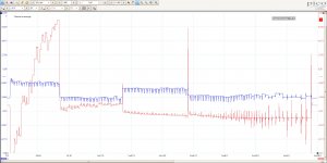
Here is the "tune" and "null" signals out of the servo loop while the instrument is doing a sweep from 120kHz to 9.5Hz (its whole range)
The "tune" signal looks reasonably well behaved. But the "null" is clearly struggling very hard in the top range. The big jumps in tune signal is when the relays toggle the tuning caps.
Tuning is done probably done exactly like on S1:
tuning.pdf - Google Drive
They have used NE5534AP with external compensation caps for the integrator opamps in the state variable filter. I'll check them out and keep you posted
An externally hosted image should be here but it was not working when we last tested it.
The "tune" signal looks reasonably well behaved. But the "null" is clearly struggling very hard in the top range. The big jumps in tune signal is when the relays toggle the tuning caps.
Tuning is done probably done exactly like on S1:
tuning.pdf - Google Drive
They have used NE5534AP with external compensation caps for the integrator opamps in the state variable filter. I'll check them out and keep you posted
I took out the two 330pF mica tuning caps and they are within tolerances.
The compensation caps are NP0 type and I took them out as well. They are also within tolerances and don't seem to care about temperature changes much.
But when I cool the NE5534AP opamps or the compensation caps in circuit the THD+n improves a lot.
I noticed that the images I upload to google drive don't get displayed on this forum properly. Opening them in new tab in Chrome works
Let me upload the loop and tune graph again directly to the forum.
Attachments
I applaud your cooling experiments. I've learned that with careful pressure on the dispense valve, I can dispense nearly drop-by-drop down the small dispensing tube. I can achieve component-specific cooling experiments in many cases.
Is distortion performance good when Null voltage near nominal?
Your sweep waveform is great technique! I'd be tempted to blame the opamp but it performs well on the lower bands.
Is distortion performance good when Null voltage near nominal?
Your sweep waveform is great technique! I'd be tempted to blame the opamp but it performs well on the lower bands.
Last edited:
The two state variable integrator opamps like to be cooled
Same with the mica caps and compensation caps. But those all measure fine out of circuit. So with cooling I can't really pinpoint the bad component.
Do you think the NE5534AP can misbehave in this way?
The THD+n loopback measurement is within specs when the null loop control voltage is within the opamp limits
Last edited:
Out of circuit component tests are not very demanding in stark contrast with distortion tests.
It's disconcerting that the problem is restricted to the top band only--- but of course that's where the mica tuning caps reside. They would be my first candidate for experimental replacement. NPO caps have a great reputation for low distortion and are available in close tolerances.
PS. I've no personal experience with NPO cap distortion. Perhaps other members can offer recommendations re manufacturer and series.
Last edited:
Jaka, if we're lucky, maybe I've stumbled across the secret sauce!
On your manual page 285, just below TABLE DIS2.3, there's discussion of trimmer cap C3501 indicating it's "adjusted at high frequencies to maintain the null control loop within its range." I was finally able to find C3501 in the schematic at location C6 on 9DIS.2000, sheet 3 of 5, page 294.
Assuming there's an equivalent cap in your instrument, maybe you'll be able to find a trimmer setting that brings all within range?
Good luck!
...I noticed that the images I upload to google drive don't get displayed on this forum properly. Opening them in new tab in Chrome works....
The tag you used is for an image, a JPG or GIF file; but you have linked a page, a Google Drive frame around an image.
Just post your G-Drive link naked. (There's other ways but this is simple.)
fullsweep.jpg - Google Drive
Last edited:
Assuming there's an equivalent cap in your instrument, maybe you'll be able to find a trimmer setting that brings all within range?
That is one of the first things I tried 😀
Unfortunately adjusting the trimmer does not improve anything, so I returned it to the original position.
But there is one thing I noticed.
Measuring the signal out of the lowpass and bandpass opamps from the filter I could see that they are 90 degrees apart as expected and this does not drift, however there is a noticeable amplitude difference between them. This of course depends on Q of the filter and I don't fully understand AP's design, but I would expect that they would want both outputs to have same amplitude when then the frequency in question is the center frequency of the filter.
The two MDAC PCBs should probably be reasonably matched (the control lines are simply wired in parallel so the CPU thinks it is setting the same value on both MDACs). The MDACs also have a trimpot.
I'm disappointed but not surprised. After posting, I thought more about the abruptly different Null waveforms at the boundary between high band and its neighbor. Seemed unlikely to cured by a component trim. Sigh.
I'm intrigued by your observation re amplitudes of lowpass and bandpass sections. How do they compare on lower bands where performance is good?
I'm intrigued by your observation re amplitudes of lowpass and bandpass sections. How do they compare on lower bands where performance is good?
- Home
- Design & Build
- Equipment & Tools
- Audio Precision Portable One Dual Domain THD+n problem