dvv,
I am surprised that you experienced problems with resistors. In our country most electronic parts sellers are in fact ordering parts from big Western European (usually German) vendors like Farnell, Digikey, Nedis, Buerklin, Conrad, Schukat, Reichlin, etc. So, even if our importers do not inspect goods as they should, Germans are doing it for us! Only if somebody from the big Western European vendors is involved in fraudulent schemes, we could get such bad parts.
That's what you think, Ivan. They will do so only if you specifically ask for it, otherwise most of what's on offer comes from Singapore, with perhaps a few exceptions here and there.
The vast majority of resistors specifically are no name products from China. Because they are cheap.
Also, German vendours are a far cry from what they used to be. Look at their catalogs - even the big names of yesteryear, such as say Buerklin, now offer like 80%+ Chinese capacitors, with just a few German made samples. Most German made products are no longer offered.
DON'T take my word for it, look for yourself.
I use Rhopoint as a supplier . Very helpful and good prices .
Rhopoint Components - Precision in Electronics
These look interesting
http://www.rhopointcomponents.com/ultra-precision-resistor-30r-to-60kr-5ppmc-epeq-series.html
Rhopoint Components - Precision in Electronics
These look interesting
http://www.rhopointcomponents.com/ultra-precision-resistor-30r-to-60kr-5ppmc-epeq-series.html
Last edited:
Hi Guys
Note that Mr.Self discusses CF and MF distortion in APAD6 pgs 45-50. His measurements confirm what many builders have known for a long time: MF is preferable if you want lowest noise and lowest THD in anything approaching an affordable build.
Ivanlukic, your list is of distributors not manufacturers. As Nigel pointed out, their catalogues are filled with Asia-supplied parts - which in itself is not a bad thing quality-wise. You get what you request from China: ask for cheap and you get cheap; ask for good but inexpensive and that's what you get. The only true sad aspect is that western business (lead by and driven by US economic interests) has crippled local manufacturing and handed technology and right-to-growth to the east. We are seeing the shift of economic power as the "US empire" slowly crumbles and China's new epoch begins.
Apart from that, you've been buying Chinese parts for a long time. Philips did not manufacture all of their catalog of components in Denmark - maybe originally, but mostly mfg shifted to Korea, Singapore, etc.
Have fun
Kevin O'Connor
I have perfectly good explanation for unexpected resistor tolerances! Some distributors have found E48 parts cheaply and they are selling them as E24 parts, so you get (for example) 1k87 instead of 1k8. They think that nobody needs precisely 1k8 and in most cases 1k87 will do just as well. They think that nobody builds RIAA circuits with 0,1dB tolerance anymore
Hi Guys
Ivanlukic, your suggestion of subbing resistors from one E range as another does not necessarily mean that those resistors will be changed. If the part is manufactured as E96, it will be marked with a 1% tolerance band. Selling it as E24, say because the distributor only wants to stock those values - does not change the manufactured part's quality.
If you mean to suggest that the manufacturer is misrepresenting an E24 part as E48 or E96, that is a different matter. It should be marked as 10%. If it is marked as 5% or 1% and sold as such then it must be counterfeit. The mfg would likely argue a "paint" problem - wrong dye or something, no subterfuge...
Distributors don't generally "think" about what anyone is building. They just track what sells and what the suppliers want to supply.
Have fun
Kevin O'Connor
Is there a reason to use anything except MF resistors?
Thx-RNMarsh
Carbon Composition resistors will withstand surges better than film types.
Metal film resistors are very slightly affected by the induced field of a very very close conductor.
Metal film resistors do not have the same range of values as other types.
So for most audio circuits metal film are the best choice.
ES
This is wrong information.Hi Guys
Ivanlukic, your suggestion of subbing resistors from one E range as another does not necessarily mean that those resistors will be changed. If the part is manufactured as E96, it will be marked with a 1% tolerance band. Selling it as E24, say because the distributor only wants to stock those values - does not change the manufactured part's quality.
If you mean to suggest that the manufacturer is misrepresenting an E24 part as E48 or E96, that is a different matter. It should be marked as 10%. If it is marked as 5% or 1% and sold as such then it must be counterfeit. The mfg would likely argue a "paint" problem - wrong dye or something, no subterfuge...
Distributors don't generally "think" about what anyone is building. They just track what sells and what the suppliers want to supply.
Have fun
Kevin O'Connor
It has been standard for a long time for manufacturers to make and offer resistors in the E24 range with the 1% tolerance (brown ring).
That is not misrepresentation.
That is a 1% tolerance resistor.
The value can come from any of the ranges, E3, E6, E12, E24, E48, E96 or any special value that is not in any of those standard ranges. All the resistor needs is the standard colour coding or numerals to indicate the claimed value, or special coding as in the manufacturer's datasheet.
Last edited:
I often buy 5% CF at $0.70 / 100 just to have the value at hand . The surprise is 95% of the time they were > more than good enough . In production I sometimes keep a few to say I understand what I am about , never a penny more than the job needs . No one ever asks ! For example I have a double current source using 2 x 39 R . As it is non critical I leave it so . The one device on that PCB of note is 10 K 0.1% . The associated components are 4M7 running 340 V DC . The best I can get is 1 % if wanting tough components . I use 4 x 4M7 in series parallel to do that ( 700 VDC rating if so ) . The 0.1% bottom arm helps a lot as it is almost a 0 . As a result the adjustment required is small . Basically the circuit requires a very stable 12 V as it's other reference which is variable . Often it will be 12.05 V . The 5% devices seem totally reliable and conservative in wattage . For production we often use MRS 25 . If the product sells well we go SMD . 10% do at a guess .
Hi Guys
Andrew, look at what I responded to before throwing out my response.
Is the full moon causing a widespread comprehension problem?
Have fun
Kevin O'Connor
Andrew, look at what I responded to before throwing out my response.
Is the full moon causing a widespread comprehension problem?
Have fun
Kevin O'Connor

In #1793 I show 2 op amps with RIAA correction and gain of 1050 ( circa 80 dB at 20 Hz ) .
The 56 dB line would be said to be - 72 db by usual ratings . It was chosen for another test .
Note how a state of the art foil resistor and Edwardian carbon comp are not so different . These are not shunted as previously by 7R and whatever inductance . The reason I show this is many will reject an idea because it goes against all instincts to try it . The conclusion must be at this gain level the resistor is not the big noise problem . The op amp is a 3.5 nV device . I have joined 3 in parallel and did get the results expected . Also the quality of noise was nicer . That seems obvious when thinking how statistical noise cancellation works . The foil resistor was on the recommendation of Lyra . I have to say my ears say it is worth the expense . Why I am clueless to say . I would suggest the foil resistor and Denon 103 might be preferable to a Lyra and MRS 25 resistor . The quest now is to find a cheaper alternative . The rest of the design is film type and that makes it more incredible . At no time did this occur to me . A friend sent the resistors and insisted I fit them . I even have a cheap switch in circuit ( Lorlin CK generic ) ! . Myself I use 47 K and no switch .
When time allows I plan to build a single input transistor op amp for this design . 2SA1085 ( RS still have them ) , 2N4403 , 2 x BC 547C . I feel it could offer - 80 dB noise . 3 x 2SA1085 input is an option . DC offset by Vbe multiplier adjustment . I have two very nice pick ups . Lyra Helikon and Ortofon MC25FL . They are different and it is impossible to say I prefer one to the other if price is considered . The FL is a calibration standard version , great for technical tests .
I do feel a minimum noise op amp section would be great in the next book ( all rules apply to power amps anyway ) . I don't feel very happy using off the shelf . An op amp optimized for ribbon mic without transformer perhaps ( DIY mic is possible ) . I did one once with my late brother ( Reslo ) . Walking around Oxford we found every electricity cable in the street . Sounded great . Common base input .
Last edited:
Many thanks for the reference.
However if I understand the authors correctly, they are saying that to the best of their knowledge Thompson was the first to use a current-mirror in the input pair collectors to perform differential-to-single-ended conversion. (sometimes called phase summing)
But the current mirror, apparently, hadn't been invented yet...
I think a Blumlein Garter circuit should have inspired someone to invent the current mirror . My guess is that transistors were expensive and unlike the Audiofools of toady the designers counted the clients pennies very carefully . Still a mystery not to see it used until op amps showed the way ( 741 I guess . Mr B W ) .Crimson Electric seemed to talk of them first ( user of output triples then ) , I think . Kendle Perry told me of them first about in 1979 at a guess ? He asked my opinion of their sonic benefits and I had no idea what they were .
Worth a look at what one of them says now it comes to mind .
http://www.diyaudio.com/forums/solid-state/134733-crimson-krimson-amp-schematics.html#post2495500
Worth a look at what one of them says now it comes to mind .
http://www.diyaudio.com/forums/solid-state/134733-crimson-krimson-amp-schematics.html#post2495500
Last edited:
But the current mirror, apparently, hadn't been invented yet...
I don't follow you.
According to Russel & Solomon, Thompson first used current-mirrors in 1966. But the Widlar variation of it was patented in 1967,which seems a bit quick.
I suspect they go back to before 1966. Anyone got any more information?
Whilst looking for a 1930? current mirror I was reminded of this 1928/9 patent . Good reading I feel .
Modulation distortion correction - TELEFUNKEN GMBH
Modulation distortion correction - TELEFUNKEN GMBH
Fire risk. In a fault condition, a tubular MF resistor used in power supplies or even the VAS and output stage of a power amplifier can glow like a radiator for quite some time before eventually disintegrating the coating and burning out. MO is the preferred grade there, as they fail quickly without flame or undue collateral damage.Is there a reason to use anything except MF resistors?....
I guess carbon film will also stay around as long it works out cheaper and remains preferred in general purpose products.
According to Russel & Solomon, Thompson first used current-mirrors in 1966.
I am not at all certain that it can be inferred from Russel & Solomon that Thompson first used current mirrors.
I am of the view that they meant the entire circuit, in which the use of a current mirror was incidental, was first used by Thompson.
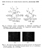
The first appearance of a 2-transitor current mirror in the Journal Of Solid-State Circuits, as best as I can tell, is in a paper by George Wilson (Dec 1968). In passing, he refers to it as a "conventional" mirror (Fig 6b) while extolling the virtues of his new 3-transistor current mirror (Fig 6a). History has subsequently named this 3-transistor circuit after its inventor: the Wilson current mirror.
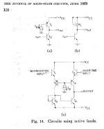
The first appearance of a differential amplifier with current mirror load in JSSC, again as best as I can tell, is in a paper by Camenzind (Mr. NE555) in June 1969. CC+CB differential input stage is loaded by a current mirror for differential-to-singleended conversion, sometimes called "phase summing": Fig 14c. In 1969 the sorry state of lateral PNPs precluded their use in common emitter topologies, so folks used them in CB and little else.
The first appearance of a differential amplifier with current mirror load in JSSC, again as best as I can tell, is in a paper by Camenzind (Mr. NE555) in June 1969. CC+CB differential input stage is loaded by a current mirror for differential-to-singleended conversion, sometimes called "phase summing": Fig 14c. In 1969 the sorry state of lateral PNPs precluded their use in common emitter topologies, so folks used them in CB and little else.
Attachments
Douglas, I have perused most of APAD6, in particular the chapter on the second stage, and found it to be enlightening to say the least. The book is worth every penny.
On the section about simulationg SOA protection, however, I would like to draw your attention to the fact that voltage source Vin (figure 24.11, pg. 567) should be connected to the top of resistor Re1; connecting the voltage source to ground introduces a slight error shown by the red trace in the attached figure; the green trace is the correct simulation result with the voltage source connected to the top of the resistor.
Additionally, your simulation model can introduce gross error unless it is calibrated. I noted this inter alia in an article published in Electronics world last year, a copy of which I sent you by email. I was, therefore, somewhat surprised that you didn't give reference to it in APAD6.
Attachments
Further, in respect of the emitter follower type 2 of fig. 9.4b (pg. 236) and the triple fig. 9.16a (pg. 247) you state somewhere, I am afraid I cannot at present remember where, that the cross-coupled drivers of fig. 9.4b do not turn off in operation. This is untrue.
It is only the first pair of cross-coupled drivers in the triple of fig. 9.16a that operate in class-A provided their cross-coupling resistor is small enough.
It is only the first pair of cross-coupled drivers in the triple of fig. 9.16a that operate in class-A provided their cross-coupling resistor is small enough.
Fire risk. In a fault condition, a tubular MF resistor used in power supplies or even the VAS and output stage of a power amplifier can glow like a radiator for quite some time before eventually disintegrating the coating and burning out. MO is the preferred grade there, as they fail quickly without flame or undue collateral damage.
There is no need to use MO resistors to make equipment that passes all the UL and European (CE) safety tests. The relatively small number of resistors that are likely to burst into flame when a test fault is applied (basically every transistor is short-circuited) are MF specified to not do this. They are often called 'fusible' resistors, and are manufactured with a fireproof cement coating.
- Home
- Amplifiers
- Solid State
- Audio Power Amplifier Design book- Douglas Self wants your opinions